2021-04-17 15:22:45 +02:00
|
|
|
# Build Guide
|
|
|
|
|
|
2021-05-15 11:20:11 +02:00
|
|
|
This is the Corne Light v1 build guide.
|
2021-04-17 15:22:45 +02:00
|
|
|
|
|
|
|
|
## Parts
|
|
|
|
|
|
|
|
|
|
<table>
|
|
|
|
|
<thead>
|
2021-05-15 08:51:41 +02:00
|
|
|
<tr> <td width = "30%"> Name </td> <td width = "15%"> Count </td> <td> Remarks </td> </tr>
|
2021-04-17 15:22:45 +02:00
|
|
|
</header>
|
|
|
|
|
<tbody>
|
|
|
|
|
<tr>
|
|
|
|
|
<td> PCB </td>
|
|
|
|
|
<td> 1 set </td>
|
|
|
|
|
<td>
|
|
|
|
|
|
|
|
|
|
</td>
|
|
|
|
|
</tr>
|
|
|
|
|
<tr>
|
|
|
|
|
<td> Top plate </td>
|
|
|
|
|
<td> 2 sheets </td>
|
|
|
|
|
<td>
|
|
|
|
|
|
|
|
|
|
</td>
|
|
|
|
|
</tr>
|
|
|
|
|
<tr>
|
|
|
|
|
<td> Bottom plate </td>
|
|
|
|
|
<td> 2 sheets </td>
|
|
|
|
|
<td rowspan = "2">
|
|
|
|
|
|
|
|
|
|
</td>
|
|
|
|
|
</tr>
|
|
|
|
|
<tr>
|
|
|
|
|
<td> ProMicro protective plate </td>
|
|
|
|
|
<td> 2 sheets </td>
|
|
|
|
|
</tr>
|
|
|
|
|
<tr>
|
|
|
|
|
<td> diode </td>
|
|
|
|
|
<td> 42 </td>
|
|
|
|
|
<td>
|
|
|
|
|
|
|
|
|
|
</td>
|
|
|
|
|
</tr>
|
|
|
|
|
<tr>
|
|
|
|
|
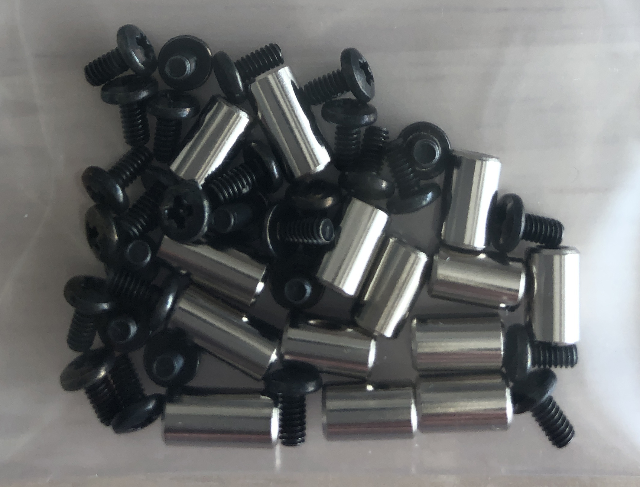
<td> Spacer M2 7.5mm </td>
|
|
|
|
|
<td> 10 </td>
|
|
|
|
|
<td rowspan = "3">
|
|
|
|
|
|
|
|
|
|
</td>
|
|
|
|
|
</tr>
|
|
|
|
|
<tr>
|
|
|
|
|
<td> Spacer M2 9mm </td>
|
|
|
|
|
<td> 4 </td>
|
|
|
|
|
</tr>
|
|
|
|
|
<tr>
|
|
|
|
|
<td> Screw M2 4mm </td>
|
|
|
|
|
<td> 28 </td>
|
|
|
|
|
</tr>
|
|
|
|
|
<tr>
|
|
|
|
|
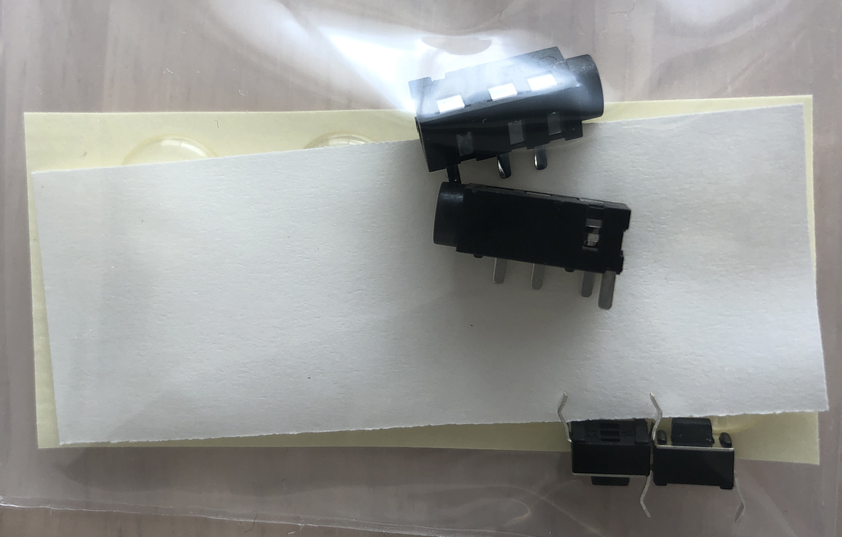
<td> TRRS jack </td>
|
|
|
|
|
<td> 2 </td>
|
|
|
|
|
<td rowspan = "3">
|
|
|
|
|
|
|
|
|
|
</td>
|
|
|
|
|
</tr>
|
|
|
|
|
<tr>
|
|
|
|
|
<td> Reset switch </td>
|
|
|
|
|
<td> 2 </td>
|
|
|
|
|
</tr>
|
|
|
|
|
<tr>
|
|
|
|
|
<td> Rubber feet </td>
|
|
|
|
|
<td> 8 </td>
|
|
|
|
|
</tr>
|
|
|
|
|
<tr>
|
|
|
|
|
<td> ProMicro (with conthrough) </td>
|
|
|
|
|
<td> 2 </td>
|
|
|
|
|
<td>
|
|
|
|
|
<a href="https://yushakobo.jp/shop/promicro-spring-pinheader/"> https://yushakobo.jp/shop/promicro-spring-pinheader/ </a>
|
|
|
|
|
</td>
|
|
|
|
|
</tr>
|
|
|
|
|
<tr>
|
|
|
|
|
<td> OLED module (with pin socket) </td>
|
|
|
|
|
<td> 2 </td>
|
|
|
|
|
<td>
|
|
|
|
|
<a href="https://yushakobo.jp/shop/oled/"> https://yushakobo.jp/shop/oled/ </a>
|
|
|
|
|
</td>
|
|
|
|
|
</tr>
|
|
|
|
|
<tr>
|
|
|
|
|
<td> key switch </td>
|
|
|
|
|
<td> 42 </td>
|
|
|
|
|
<td> </td>
|
|
|
|
|
</tr>
|
|
|
|
|
<tr>
|
|
|
|
|
<td> keycap </td>
|
|
|
|
|
<td> 42 </td>
|
|
|
|
|
<td> </td>
|
|
|
|
|
</tr>
|
|
|
|
|
<tr>
|
|
|
|
|
<td> TRRS cable </td>
|
|
|
|
|
<td> 1 </td>
|
|
|
|
|
<td> TRS cable is also acceptable </td>
|
|
|
|
|
</tr>
|
|
|
|
|
<tr>
|
|
|
|
|
<td> USB cable </td>
|
|
|
|
|
<td> 1 </td>
|
|
|
|
|
<td> </td>
|
|
|
|
|
</tr>
|
|
|
|
|
</tbody>
|
|
|
|
|
</table>
|
|
|
|
|
|
|
|
|
|
## Advance preparation
|
|
|
|
|
|
|
|
|
|
If you build the firmware yourself,
|
|
|
|
|
it takes time to prepare the environment,
|
|
|
|
|
so it is recommended to start first. \
|
2021-05-15 11:20:11 +02:00
|
|
|
See <https://github.com/foostan/crkbd/blob/master/doc/firmware_en.md>
|
|
|
|
|
for more information.
|
2021-04-17 15:22:45 +02:00
|
|
|
|
|
|
|
|
## Implementation
|
|
|
|
|
|
|
|
|
|
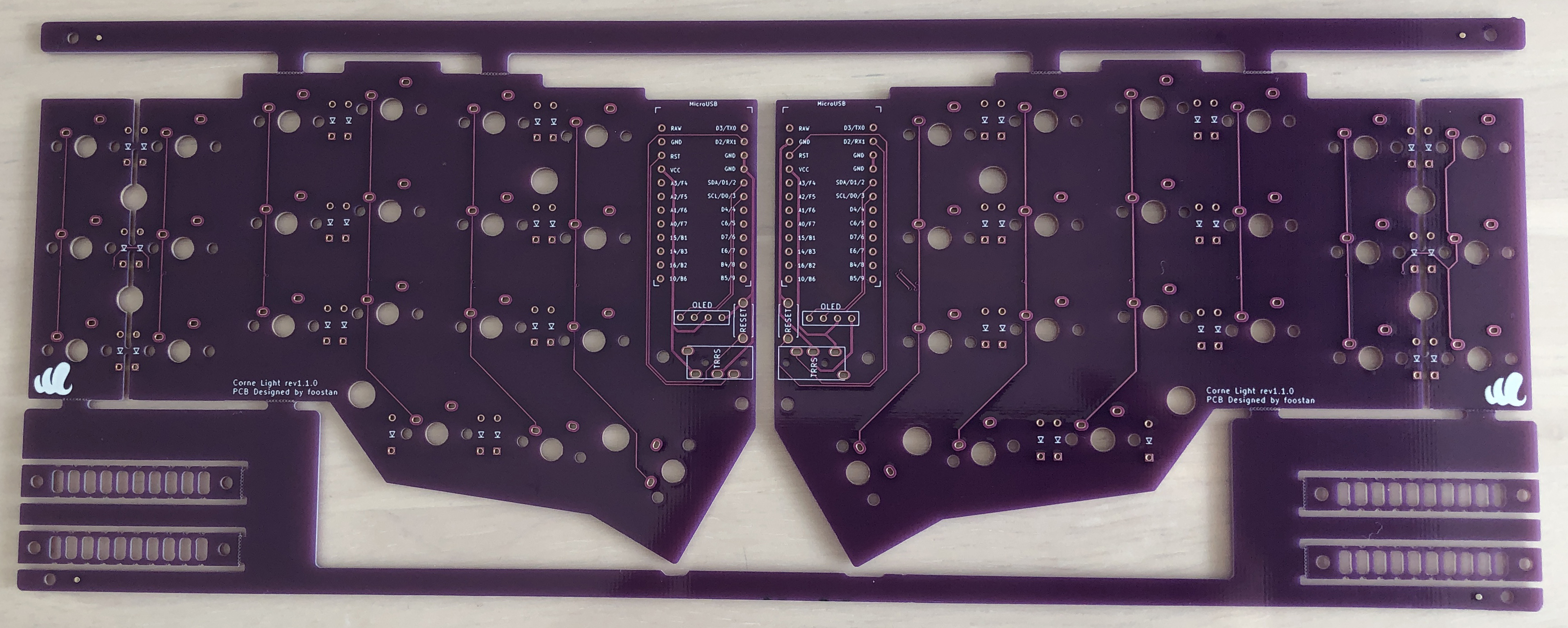
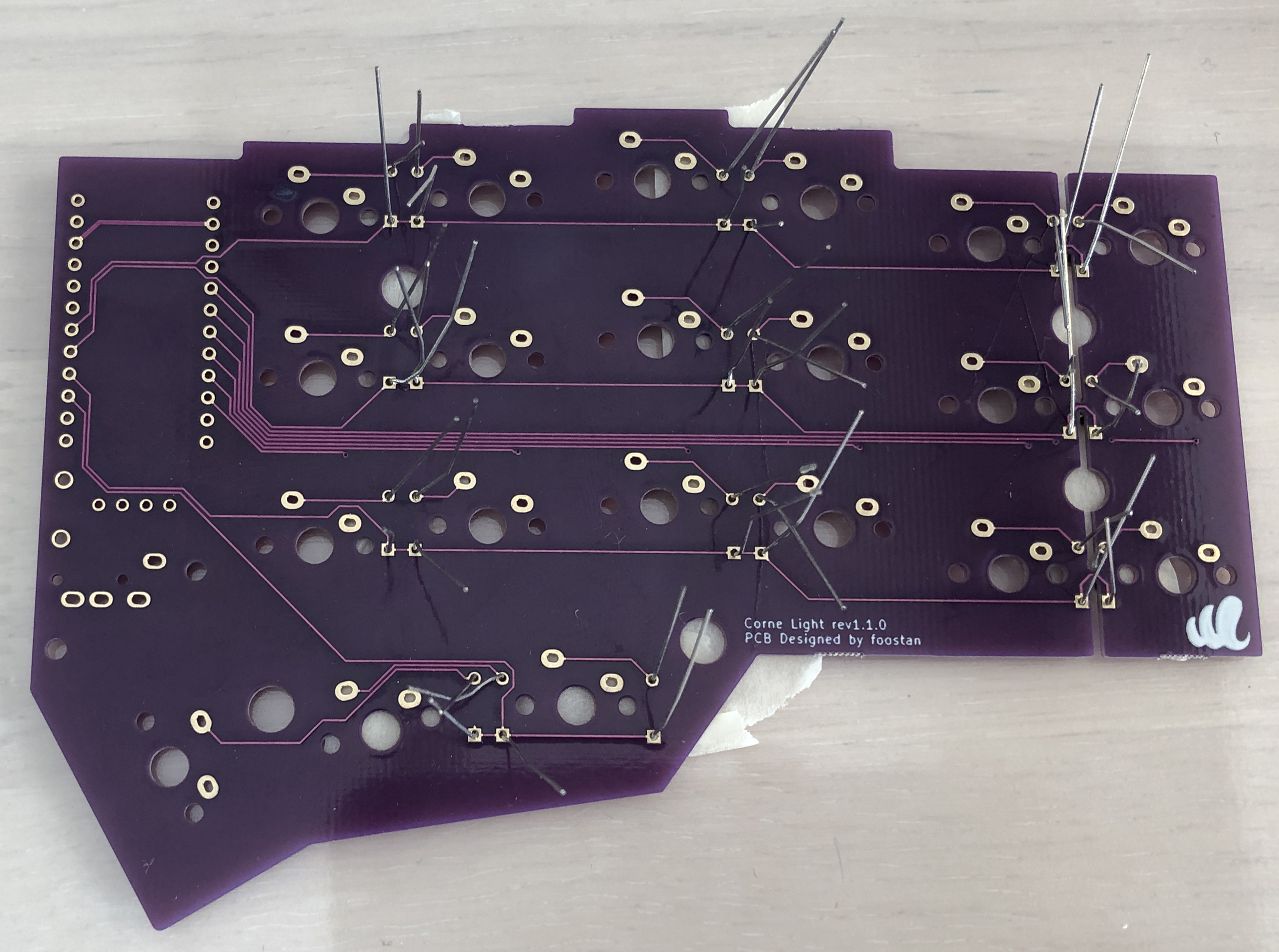
### PCB disconnection
|
|
|
|
|
|
|
|
|
|
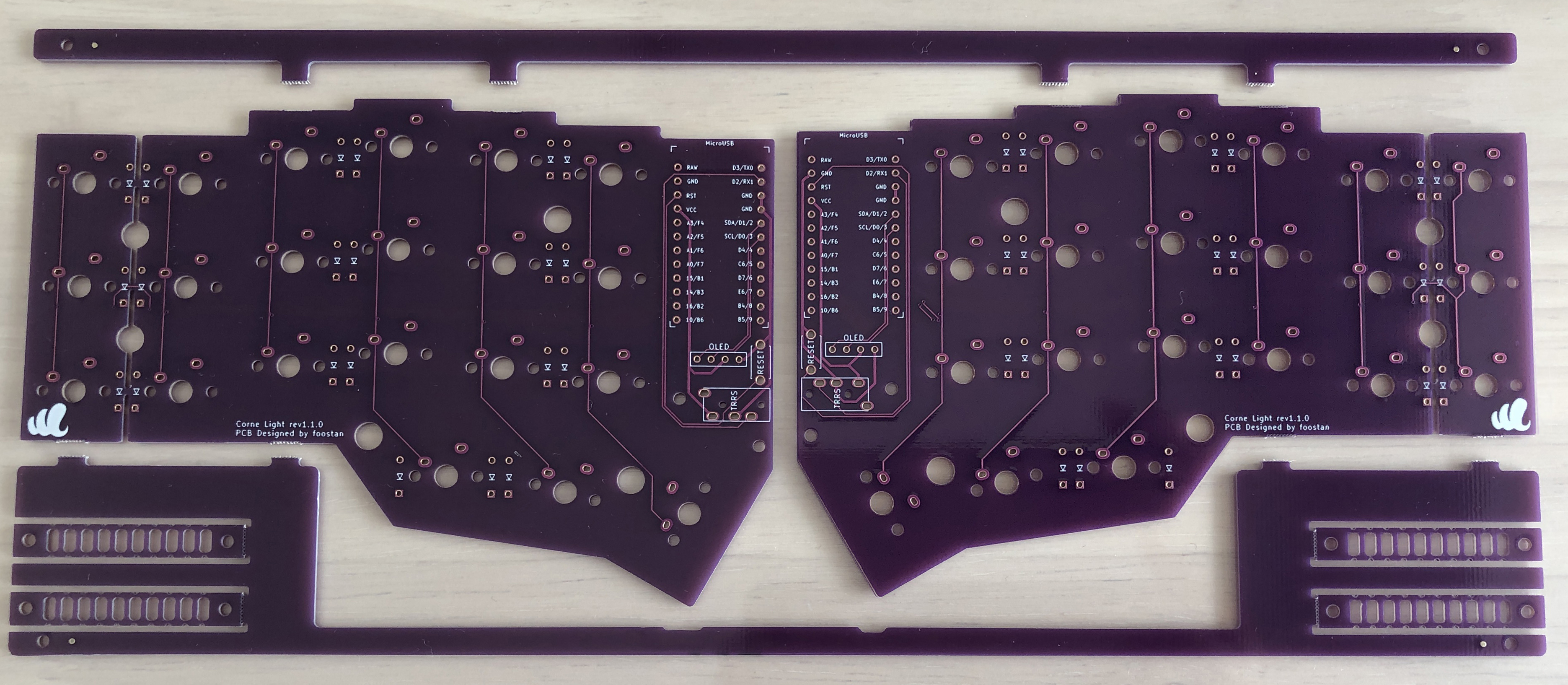
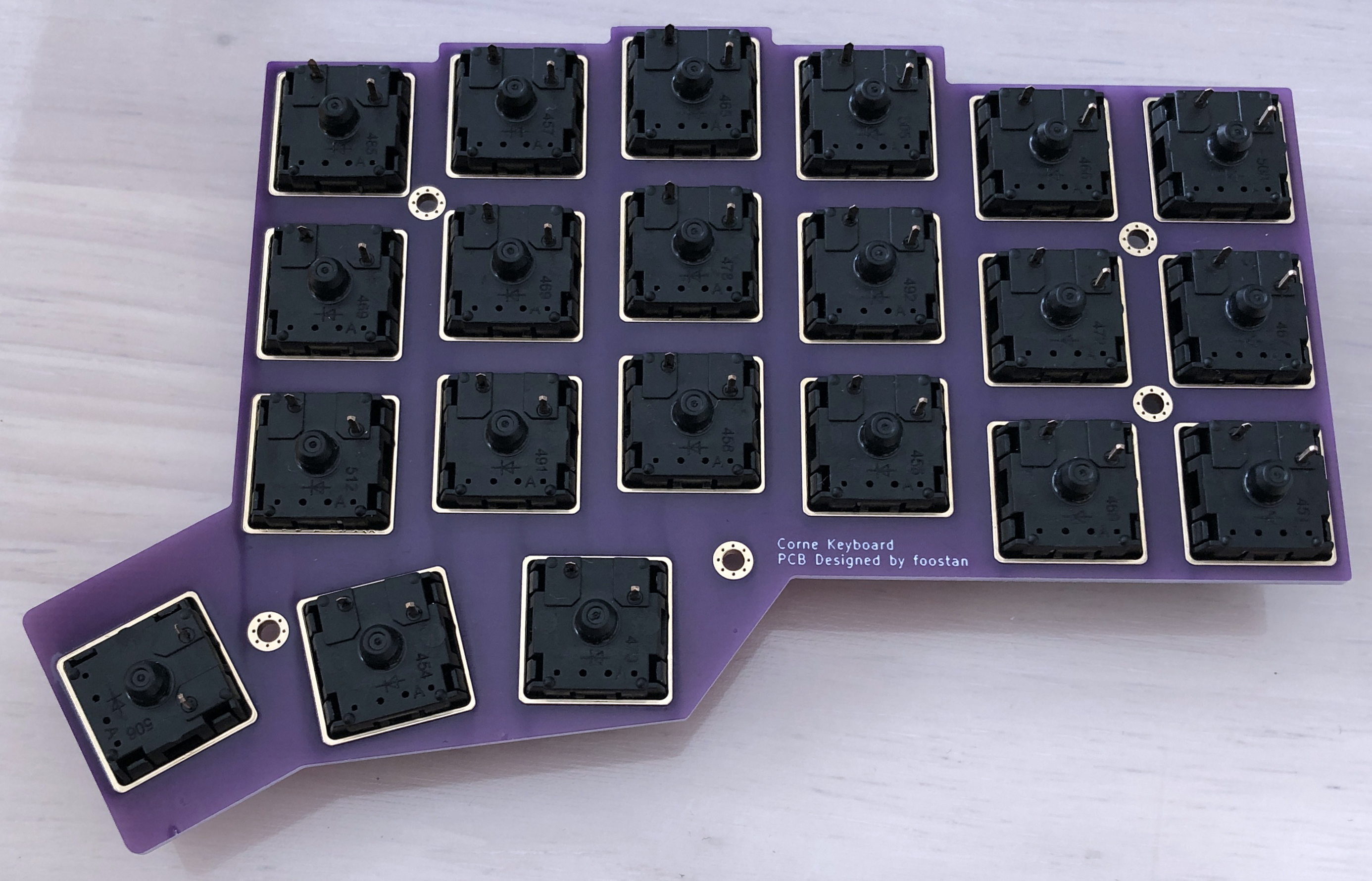
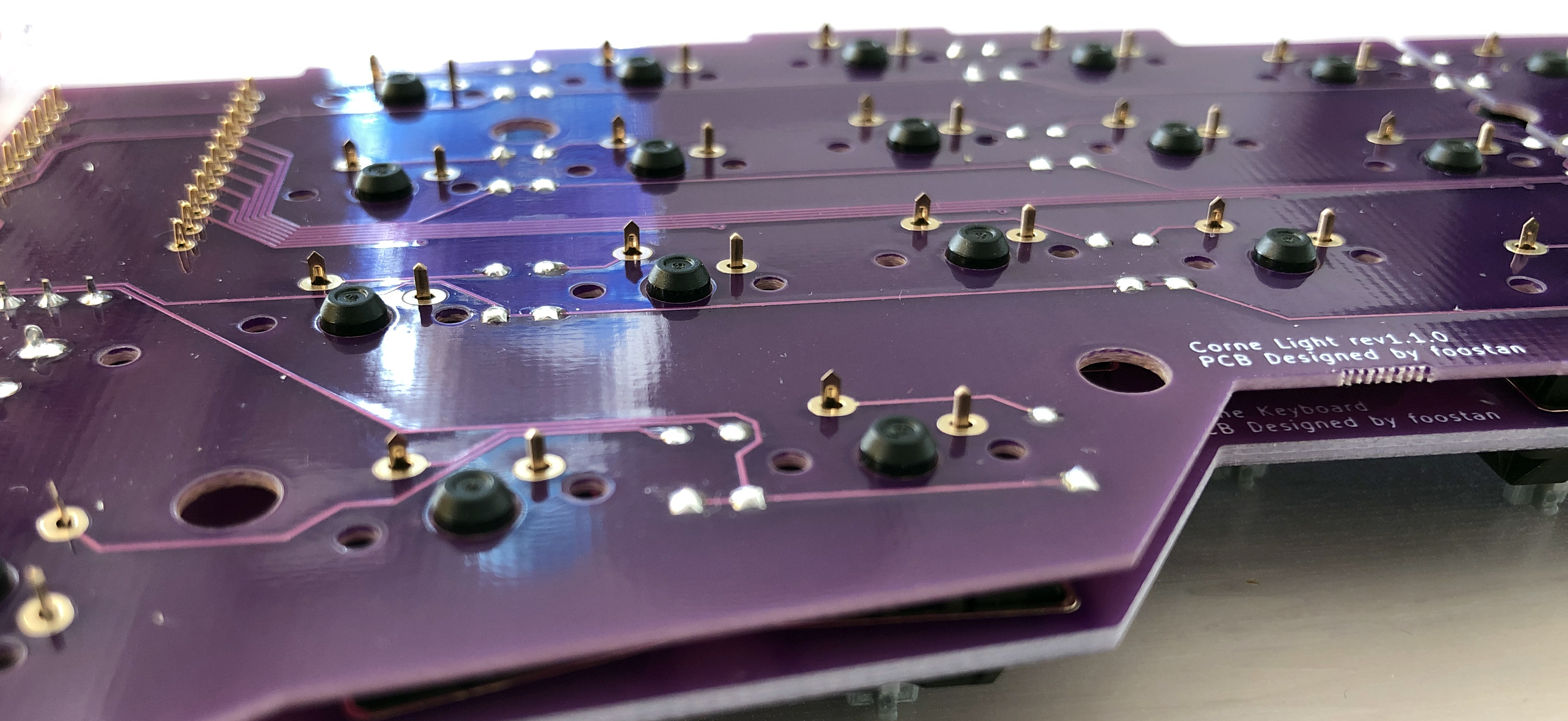
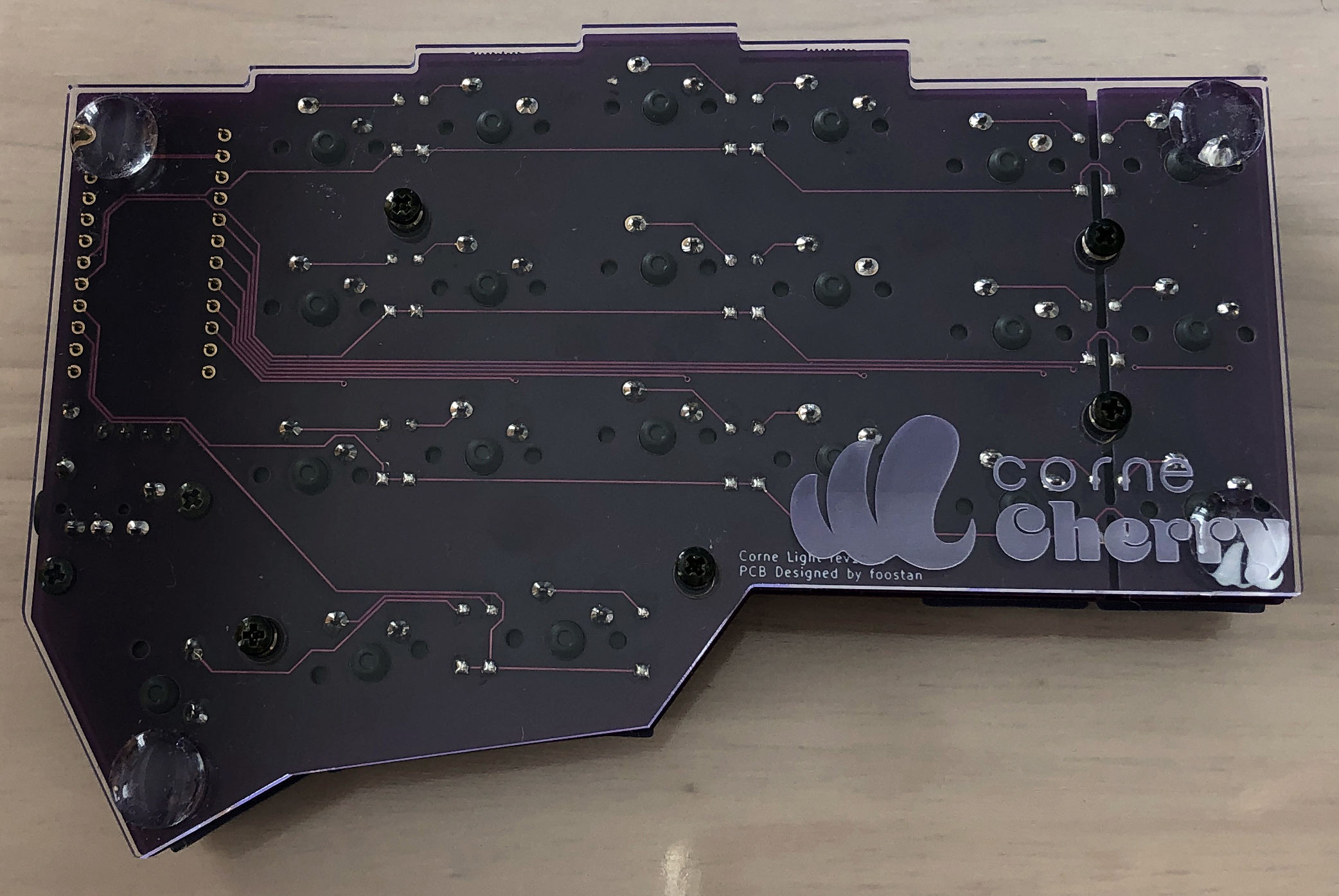
Check the front and back and separate the left and right PCBs
|
|
|
|
|
(the photo is the front).
|
|
|
|
|
|
|
|
|
|
|
|
|
|
|
|
|
|
|
|
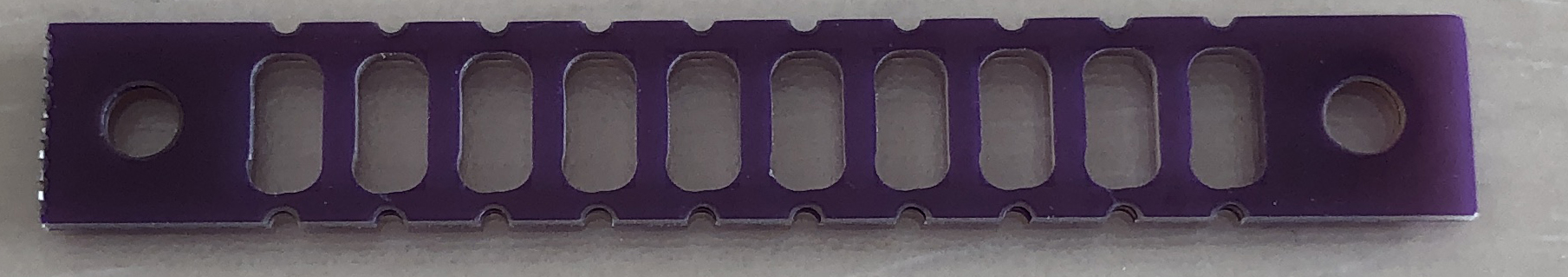
This is a jig for bending the legs of a diode.
|
|
|
|
|
Separate it if necessary.
|
|
|
|
|
|
|
|
|
|
|
|
|
|
|
|
|
|
|
|
* Some versions do not have a jig.
|
|
|
|
|
|
2021-05-15 08:52:32 +02:00
|
|
|
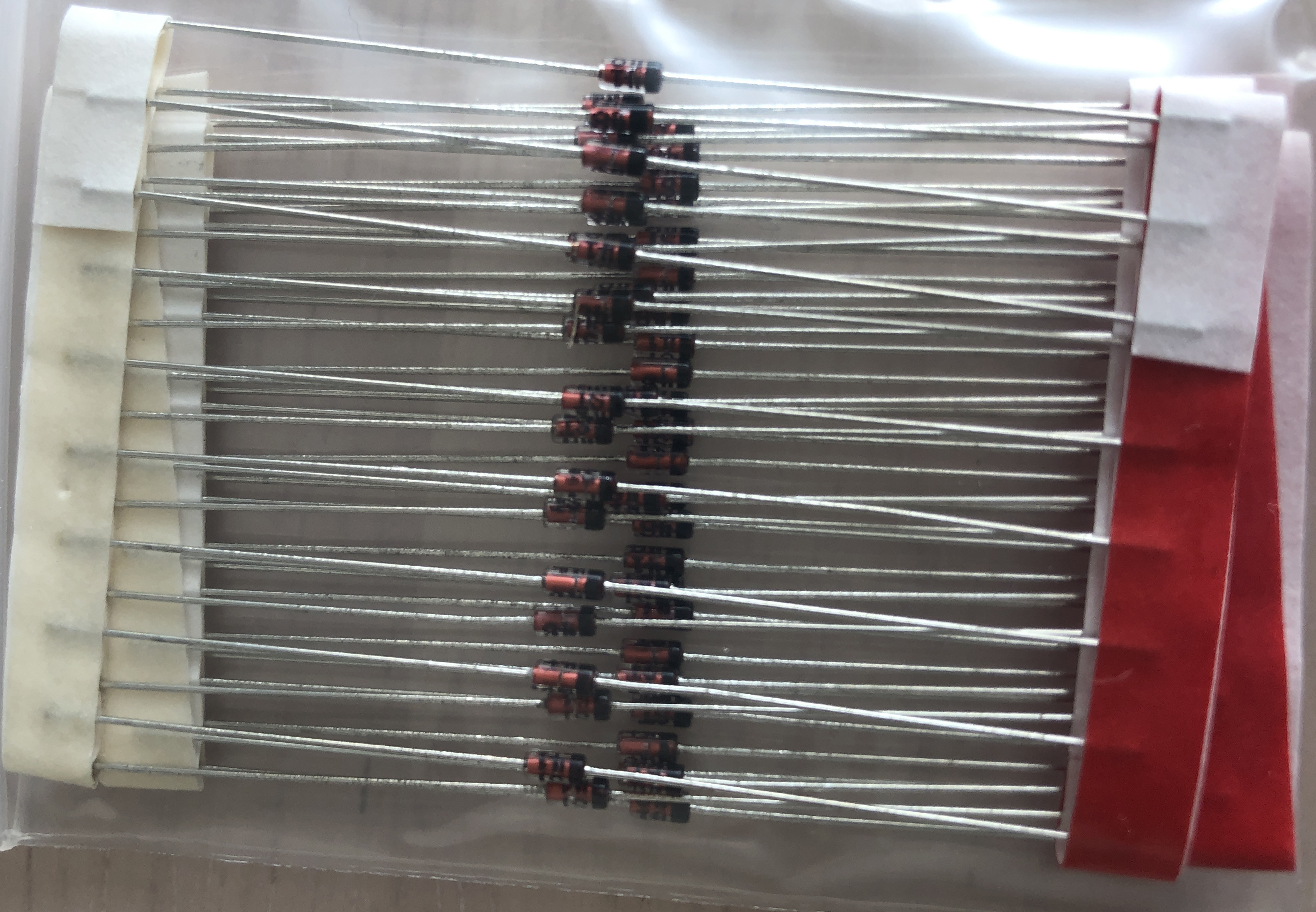
### Diodes
|
2021-04-17 15:22:45 +02:00
|
|
|
|
|
|
|
|
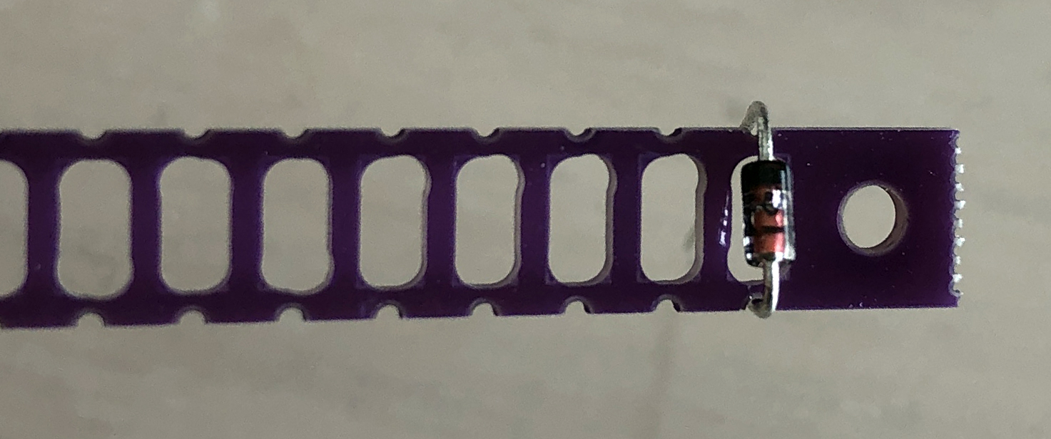
First, bend the legs of the reed type diode.
|
|
|
|
|
|
|
|
|
|
* You can clean it by bending it one by one as shown in the picture,
|
|
|
|
|
but it is more efficient to bend multiple pieces at the same time
|
|
|
|
|
while connected to the tape.
|
|
|
|
|
|
|
|
|
|
|
|
|
|
|
|
|
|
|
|
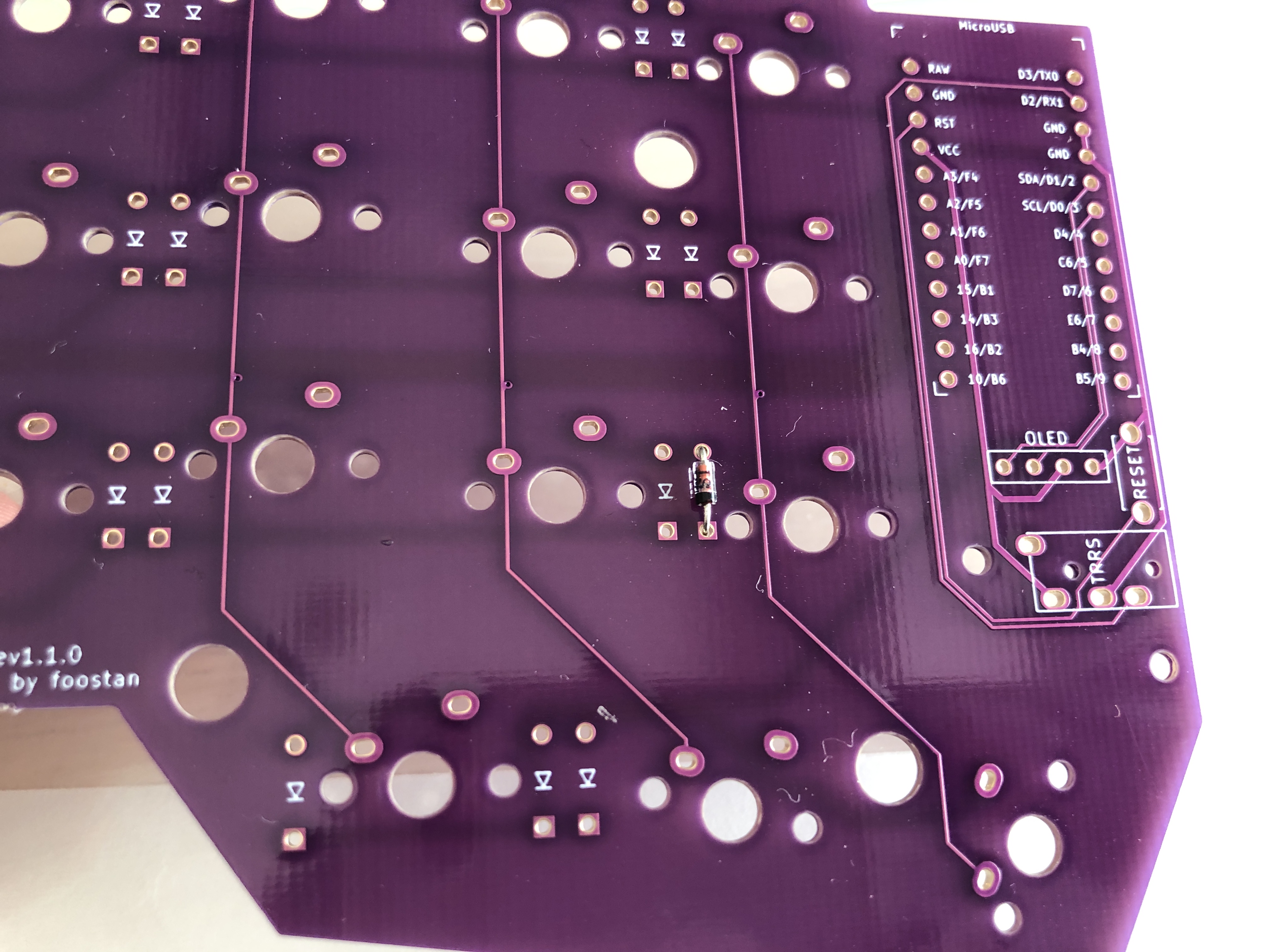
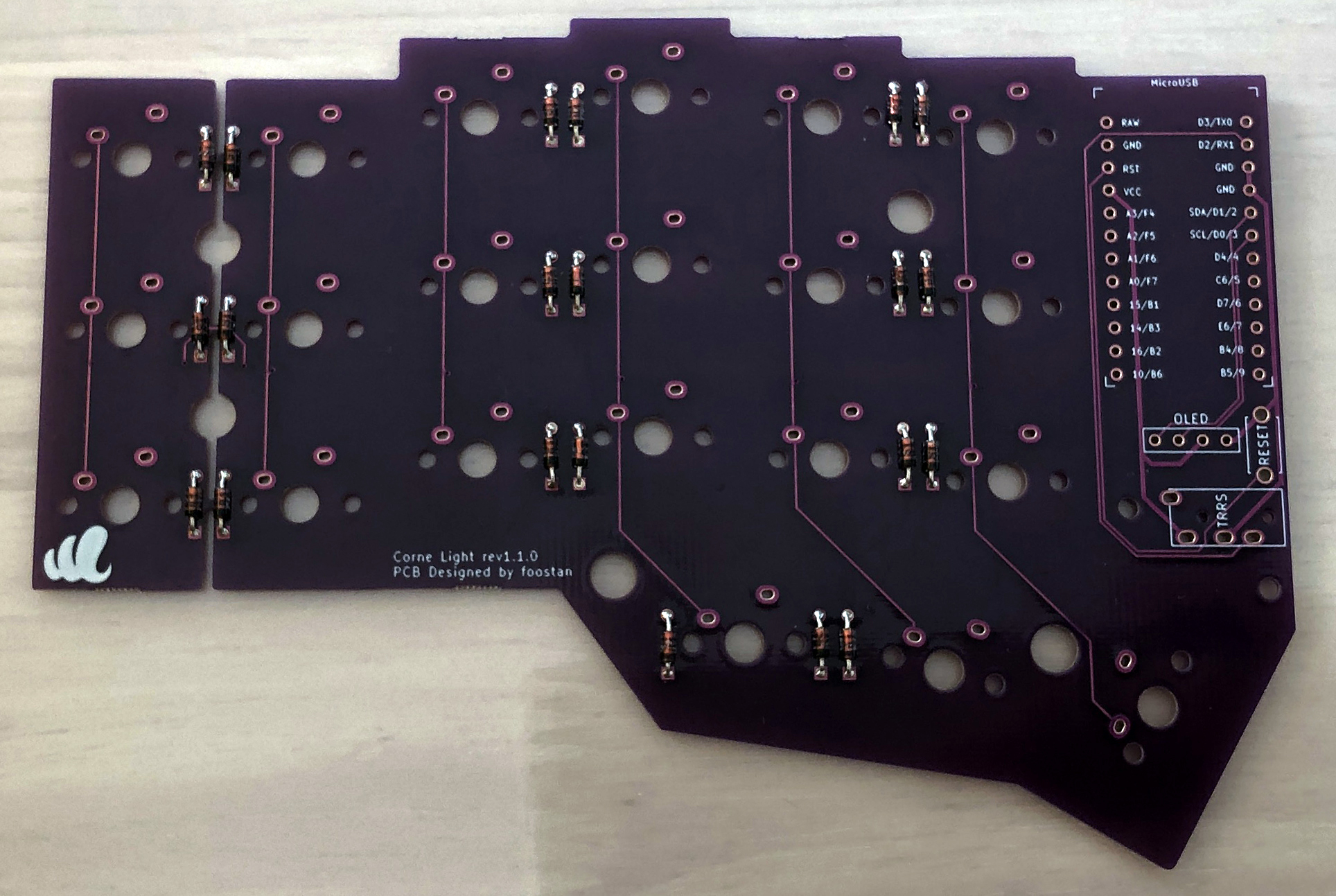
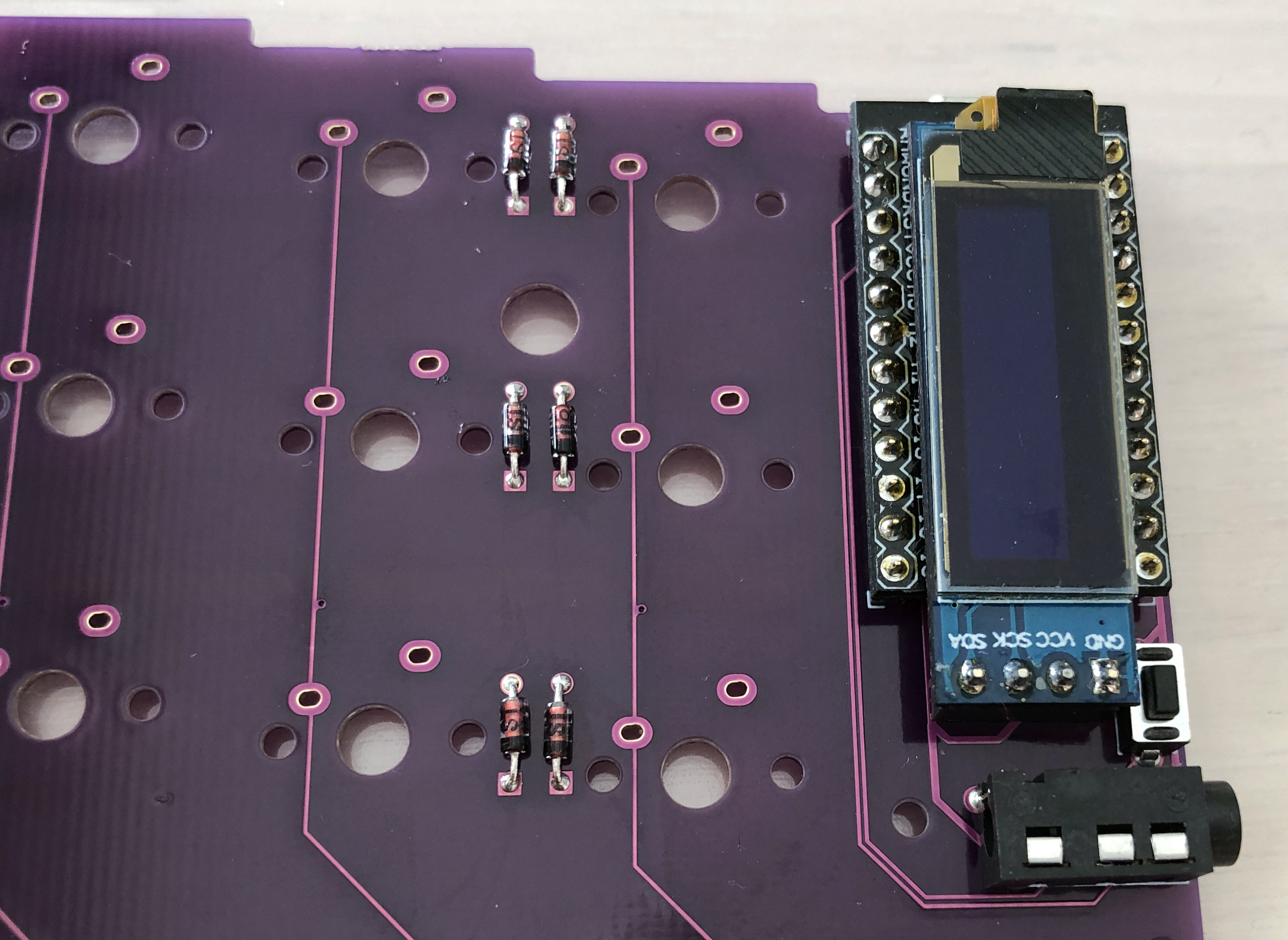
Attach the diode with the bent leg to the specified position.
|
|
|
|
|
|
|
|
|
|
|
|
|
|
|
|
|
|
|
|
The diode has an orientation and is installed as shown in the photo.
|
|
|
|
|
|
|
|
|
|
* All the diodes to be attached are in the same orientation.
|
|
|
|
|
|
|
|
|
|
|
|
|
|
|
|
|
|
|
|
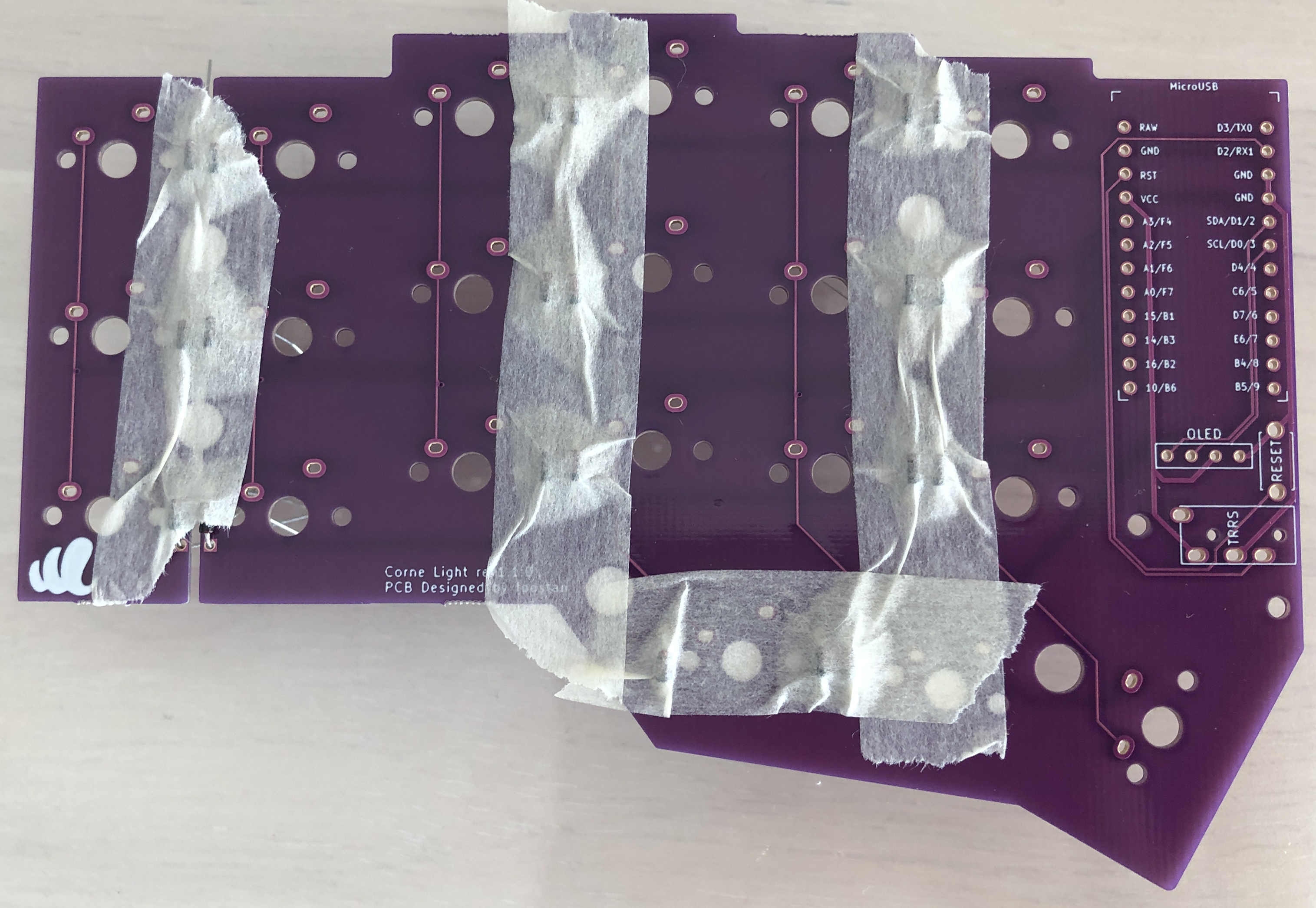
You can attach it neatly by fixing it with masking tape.
|
|
|
|
|
|
|
|
|
|
|
|
|
|
|
|
|
|
|
|
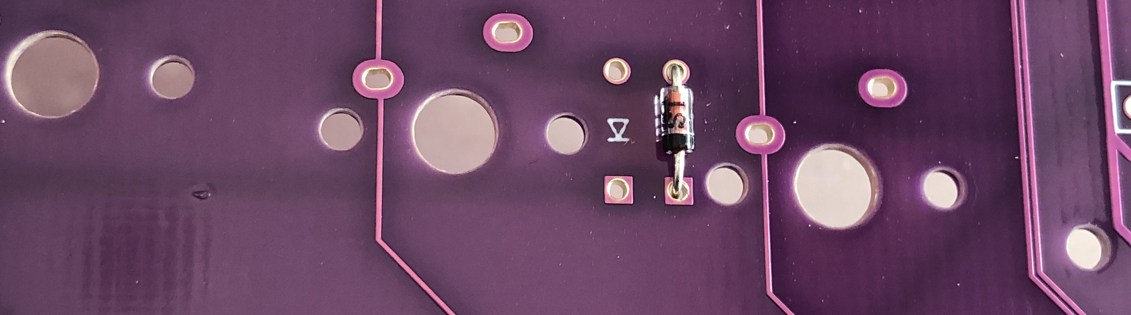
Solder from the back side.
|
|
|
|
|
|
|
|
|
|
|
|
|
|
|
|
|
|
|
|
If you are fixing with masking tape,
|
|
|
|
|
cutting your legs to the limit like this will make soldering easier.
|
|
|
|
|
|
|
|
|
|
|
|
|
|
|
|
|
|
|
|
With 21 one-handed and two-handed he installs 42 diodes.
|
|
|
|
|
|
|
|
|
|
|
|
|
|
|
|
|
|
|
|
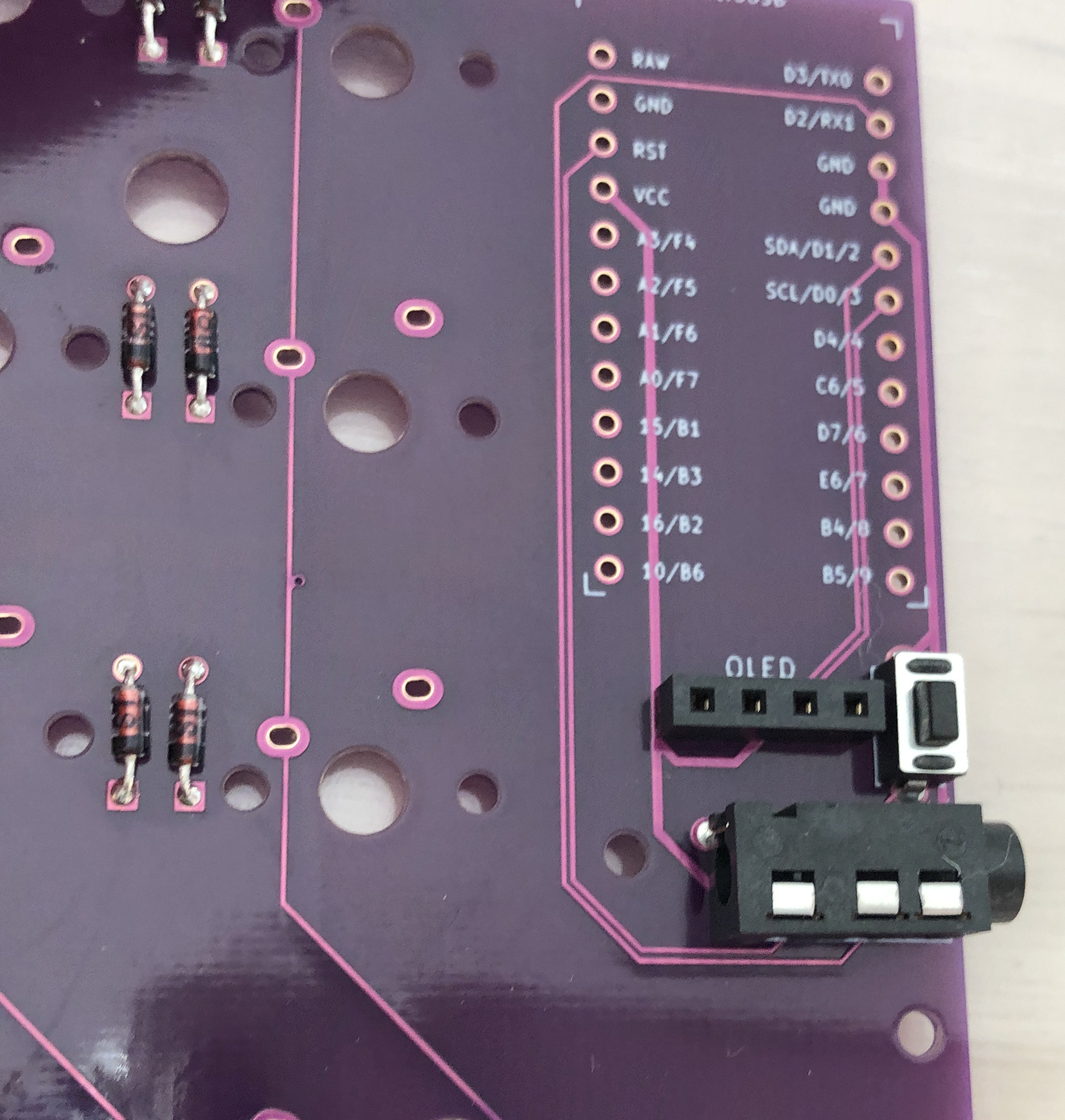
### TRRS jack, reset switch, pin socket
|
|
|
|
|
|
|
|
|
|
Install in the specified position.
|
|
|
|
|
|
|
|
|
|
* Install the right hand side in the same position
|
|
|
|
|
(be careful of mistakes on the front and back).
|
|
|
|
|
|
|
|
|
|
|
|
|
|
|
|
|
|
|
|
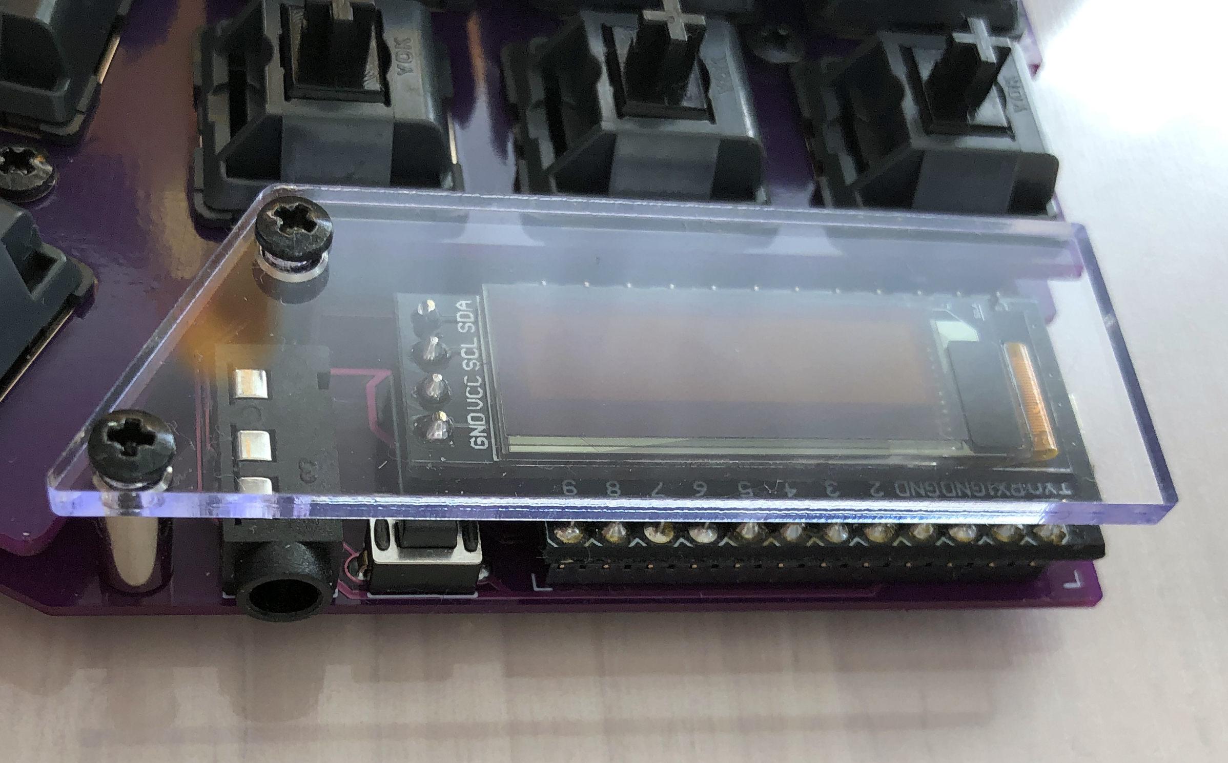
### ProMicro, OLED module
|
|
|
|
|
|
|
|
|
|
Install his ProMicro and his OLED module by referring to the [Helix Build Guide](
|
|
|
|
|
https://github.com/MakotoKurauchi/helix/blob/master/Doc/buildguide_en.md#pro-micro).
|
|
|
|
|
|
|
|
|
|
|
|
|
|
|
|
2021-05-15 11:20:11 +02:00
|
|
|
### Firmware
|
2021-04-17 15:22:45 +02:00
|
|
|
|
|
|
|
|
Write the firmware to ProMicro by referring to the following. \
|
|
|
|
|
<https://github.com/foostan/crkbd/blob/master/doc/firmware_en.md>
|
|
|
|
|
|
|
|
|
|
### Operation check
|
|
|
|
|
|
|
|
|
|
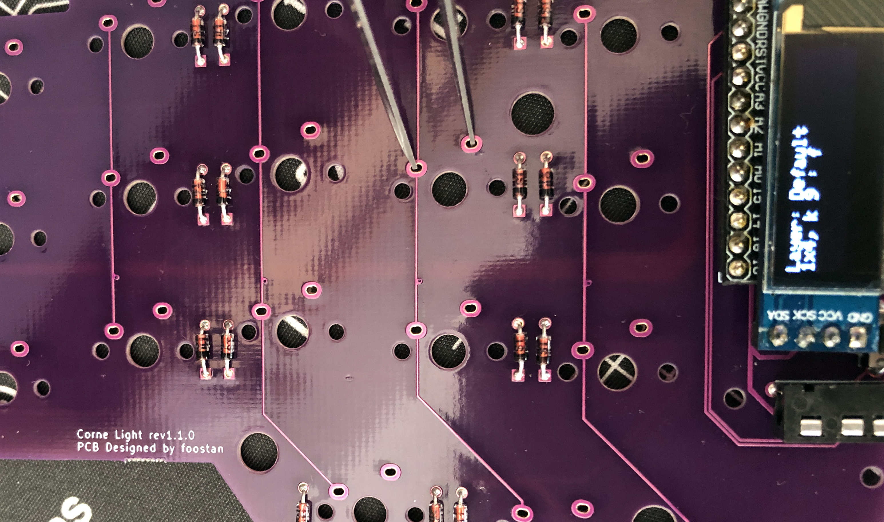
To check the operation,
|
|
|
|
|
connect the left hand side to the PC with a USB cable,
|
2021-05-15 11:20:11 +02:00
|
|
|
and connect the left hand side and the right hand side with the TRRS cable.
|
2021-04-17 15:22:45 +02:00
|
|
|
Since there may be defects such as jacks,
|
2021-05-15 11:20:11 +02:00
|
|
|
be sure to connect the left and right instead of one by one
|
|
|
|
|
before checking the operation.
|
2021-04-17 15:22:45 +02:00
|
|
|
|
|
|
|
|
* Since the switch is not attached,
|
|
|
|
|
check the operation with tweezers as shown in the photo.
|
|
|
|
|
|
|
|
|
|
|
|
|
|
|
|
|
|
|
|
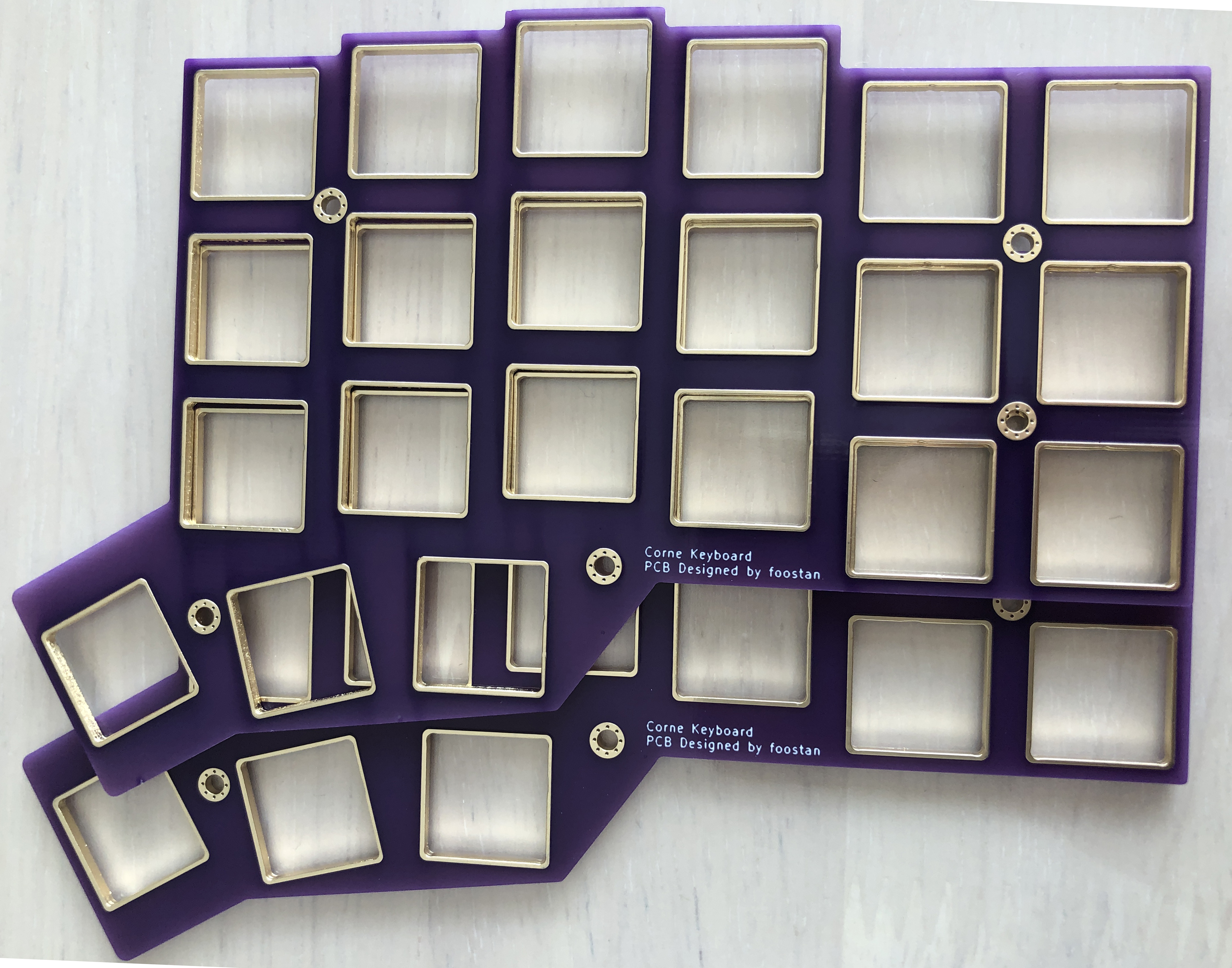
### Top plate, key switch
|
|
|
|
|
|
|
|
|
|
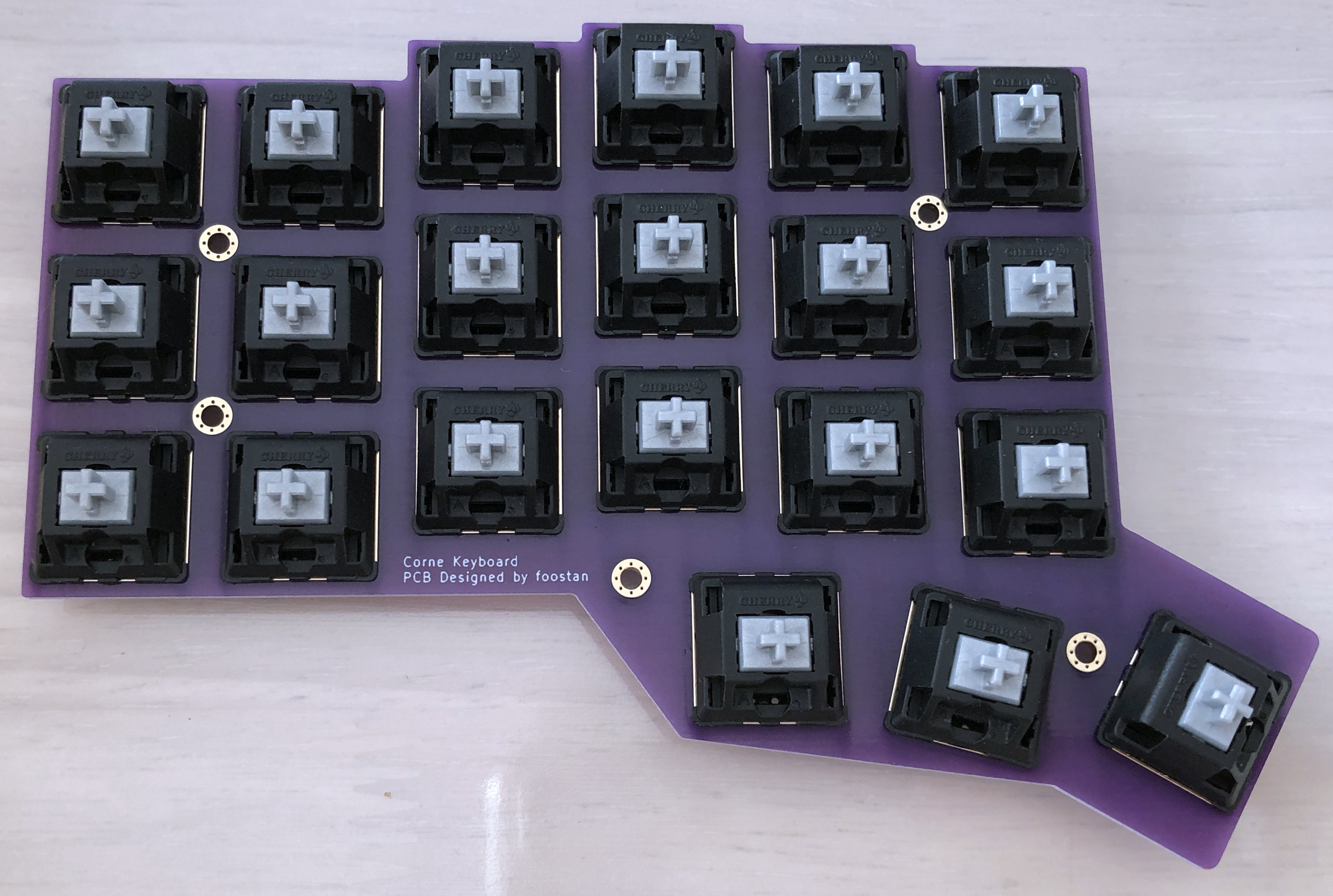
Attach the key switch to the top plate as shown in the picture.
|
|
|
|
|
|
|
|
|
|
* Be careful of the direction of the key switch.
|
|
|
|
|
|
|
|
|
|
|
|
|
|
|
|
|
|
|
|
We recommend using a 3-pin key switch.
|
|
|
|
|
|
|
|
|
|
* Even when using 5 pins, the plastic legs can be separated to make 3 pins.
|
|
|
|
|
|
|
|
|
|
|
|
|
|
|
|
|
|
|
|
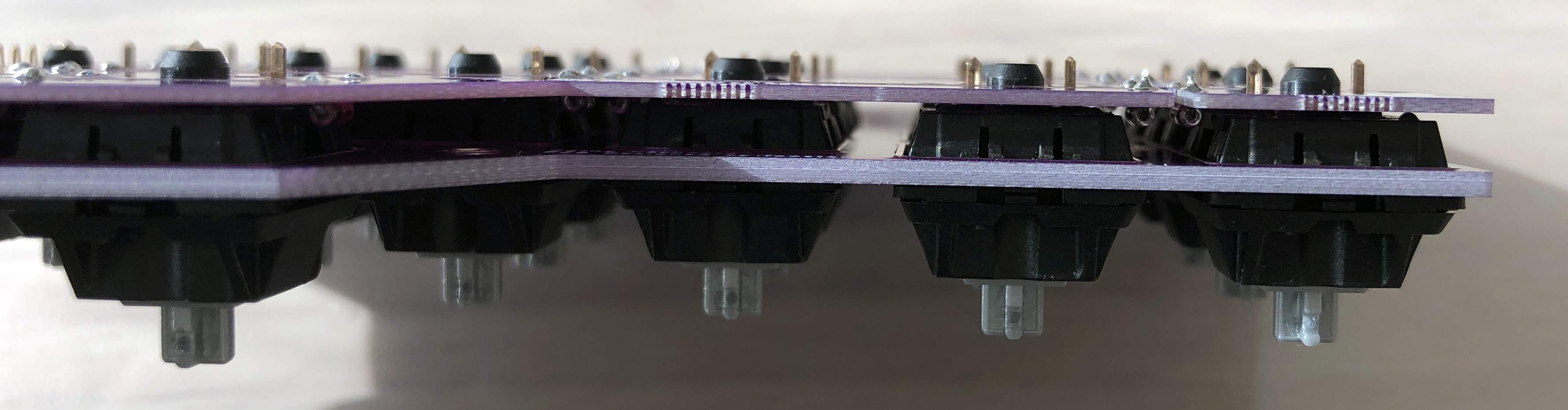
Solder so that there is no gap between the switch and the PCB.
|
|
|
|
|
|
|
|
|
|
|
|
|
|
|
|
|
|
|
|
|
|
|
|
|
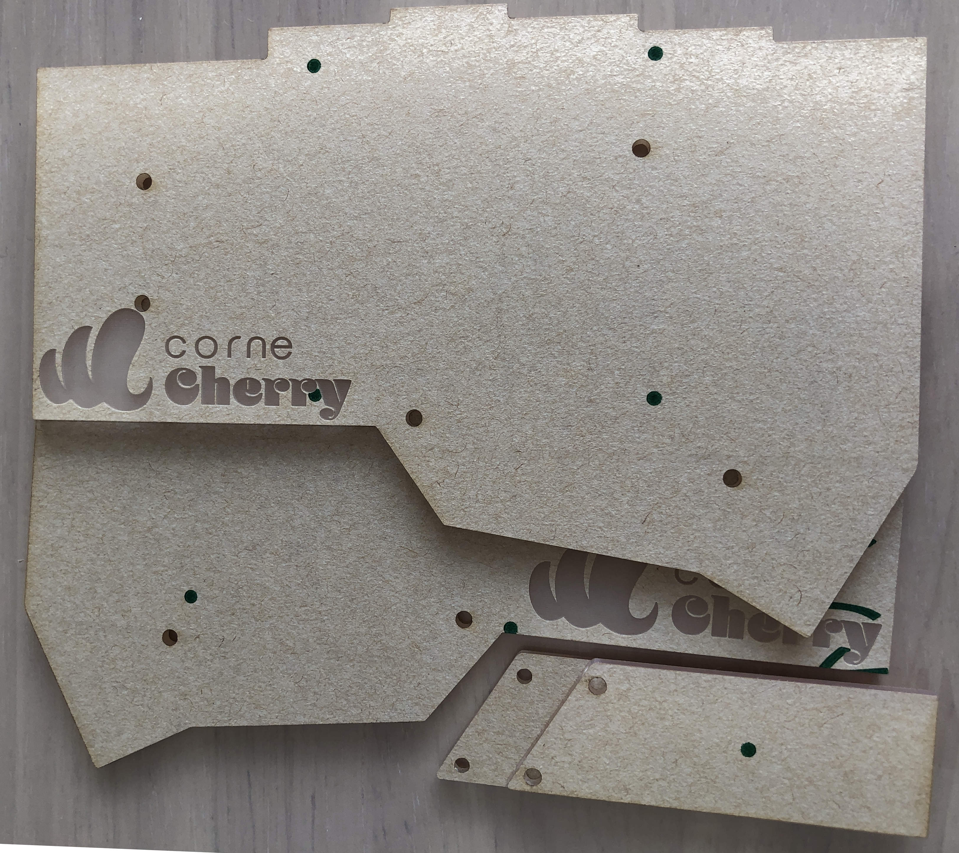
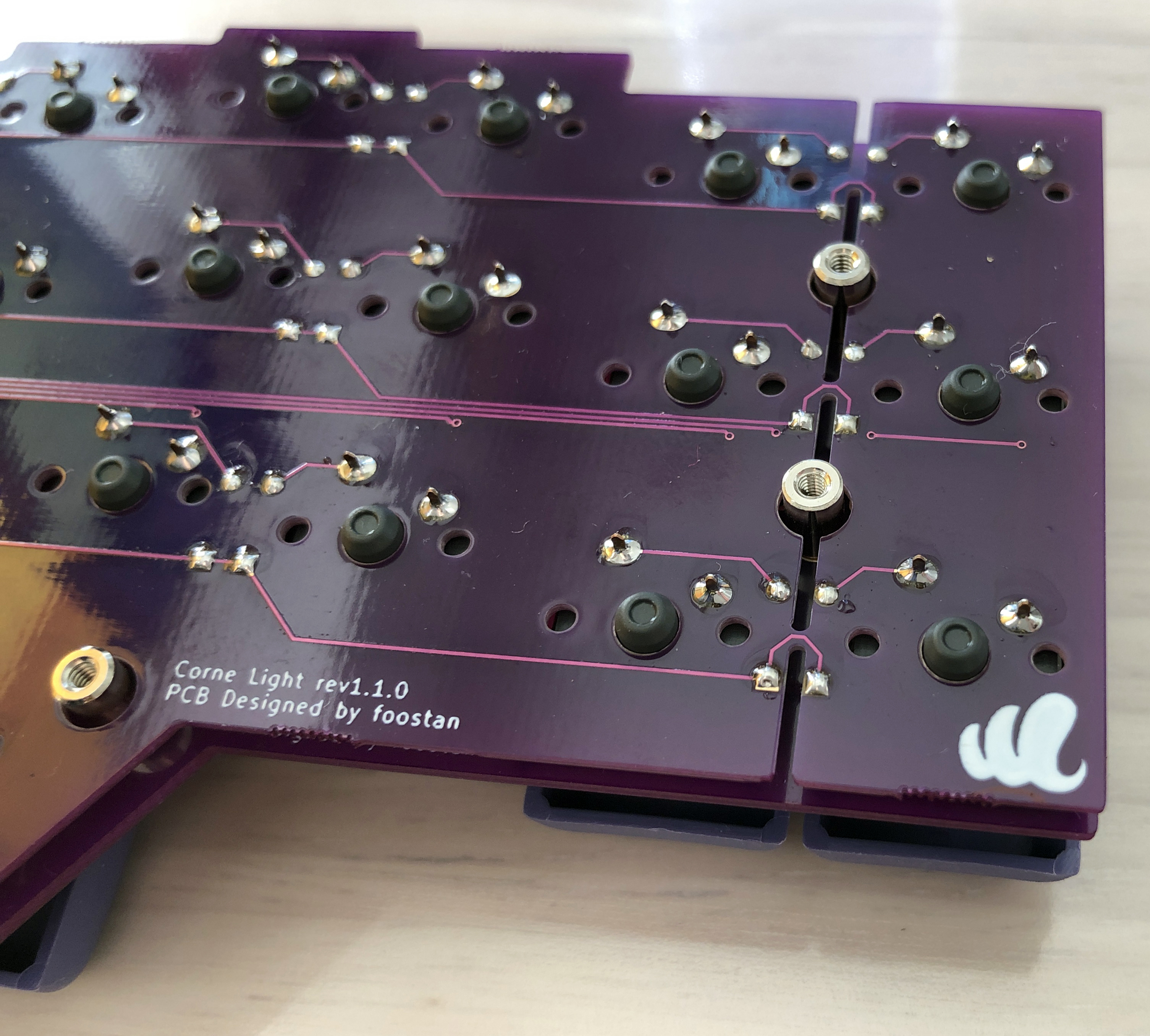
### ProMicro Protective Plate, Bottom Plate
|
|
|
|
|
|
|
|
|
|
Attach his ProMicro protective plate using an M2 9mm spacer.
|
|
|
|
|
|
|
|
|
|
|
|
|
|
|
|
|
|
|
|
Install the bottom plate using the M2 7.5mm spacer.
|
|
|
|
|
|
|
|
|
|
|
|
|
|
|
|
|
|
|
|
Attach the rubber feet to the four corners.
|
|
|
|
|
|
|
|
|
|
|
|
|
|
|
|
|
|
|
|
## Complete
|
|
|
|
|
|
|
|
|
|
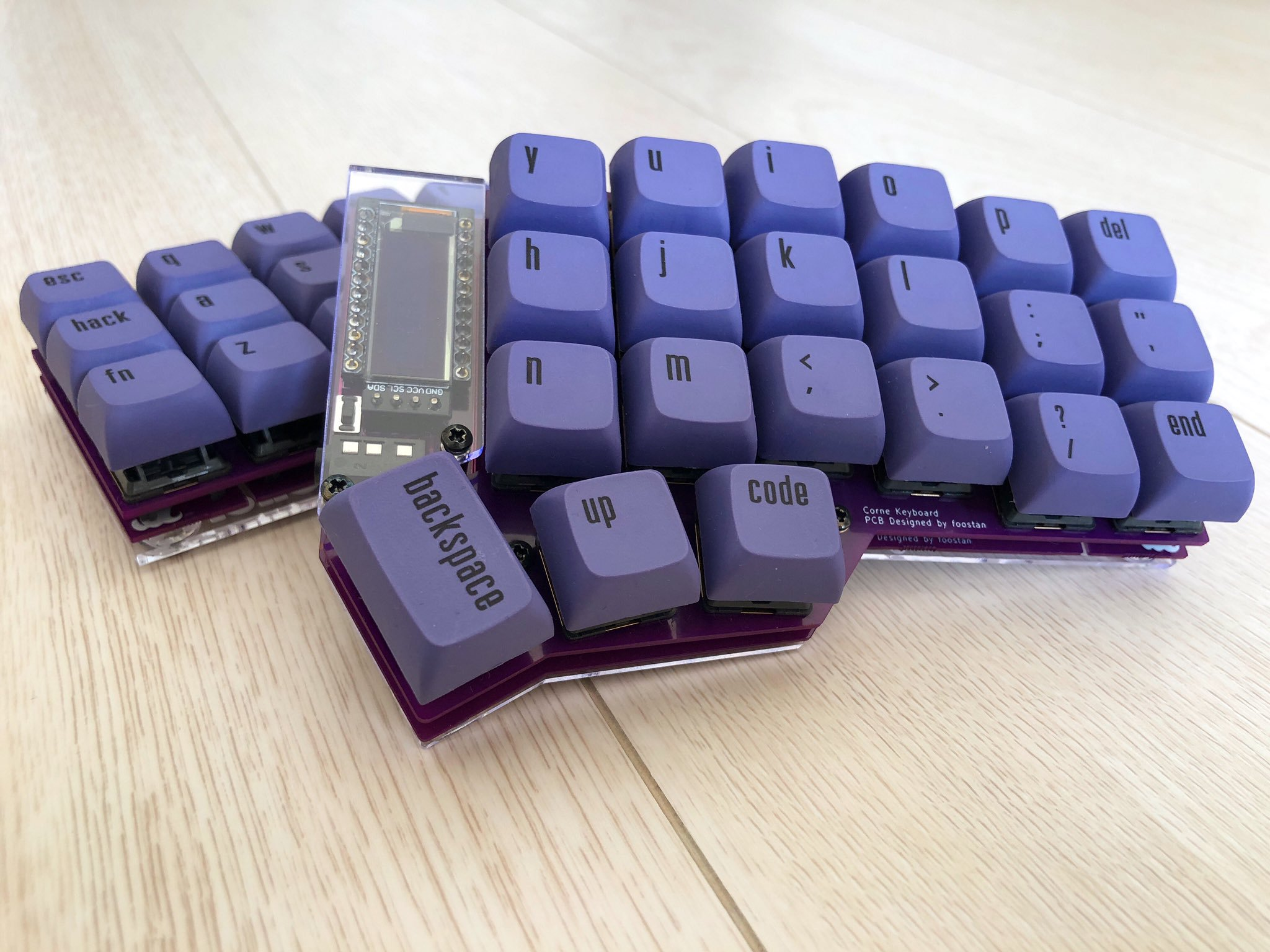
Attach the keycap and you're done.
|
|
|
|
|
|
|
|
|
|
|
|
|
|
|
|