2021-04-17 15:22:45 +02:00
|
|
|
# Build Guide
|
|
|
|
|
|
|
|
|
|
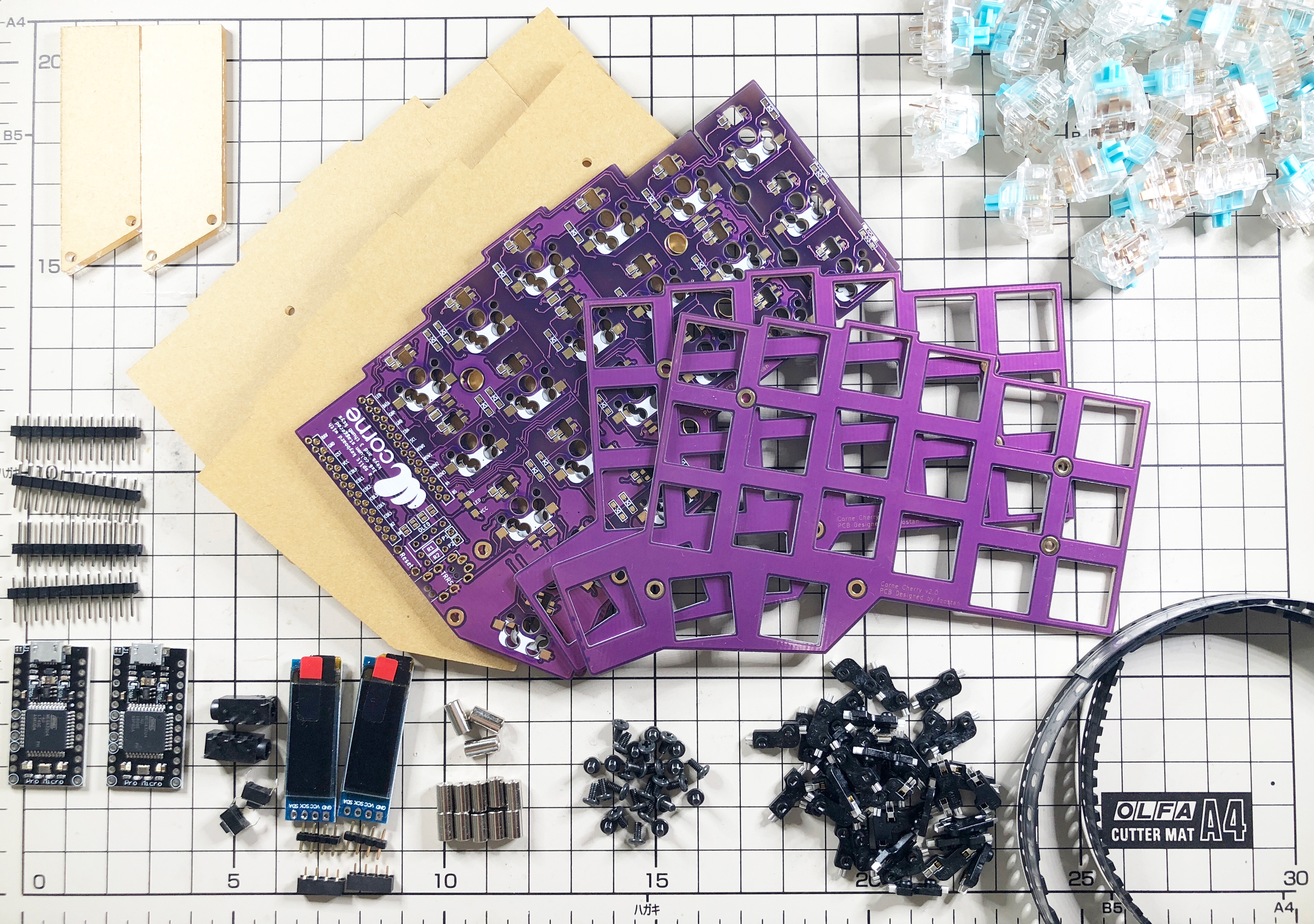
This is the build guide for Corne Cherry v2.
|
2021-05-15 11:20:11 +02:00
|
|
|
[Click here for the Corne Cherry v3 build guide](
|
2021-04-17 15:22:45 +02:00
|
|
|
https://github.com/foostan/crkbd/blob/master/corne-cherry/doc/v3/buildguide_en.md).
|
|
|
|
|
|
|
|
|
|
## Parts
|
|
|
|
|
|
|
|
|
|
### Required
|
|
|
|
|
|
2021-05-15 08:51:41 +02:00
|
|
|
| Name | Count | Remarks |
|
2021-04-17 15:22:45 +02:00
|
|
|
|:-|:-|:-|
|
|
|
|
|
| PCB | 2 sheets | |
|
|
|
|
|
| Top plate | 2 sheets | |
|
|
|
|
|
| Bottom plate | 2 sheets | PCB type and acrylic type can be selected |
|
|
|
|
|
| ProMicro protective plate | 2 sheets | |
|
|
|
|
|
| ProMicro | 2 sheets | |
|
|
|
|
|
| TRRS jack | 2 | |
|
|
|
|
|
| Tact switch | 2 | |
|
|
|
|
|
| Diodes | 42 | Only chip parts |
|
|
|
|
|
| Kailh PCB Sockets | 42 | |
|
|
|
|
|
| Key switches | 42 | Only compatible with CherryMX |
|
|
|
|
|
| Keycaps | 42 pcs | 1u 40 pcs, 1.5u 2 pcs |
|
|
|
|
|
| OLED module | 2 sheets | |
|
|
|
|
|
| 4 pin headers | 2 | |
|
|
|
|
|
| 4 pin sockets | 2 | |
|
|
|
|
|
| Spacer M2 7.5mm | 10 pieces | |
|
|
|
|
|
| Spacer M2 9mm | 4 pieces | |
|
|
|
|
|
| Screw M2 4mm | 28 screws | |
|
|
|
|
|
| Cushion rubber | 8 pieces | |
|
|
|
|
|
| TRS (3-pole) cable | 1 | TRRS (4-pole) cable is also acceptable |
|
|
|
|
|
| Micro USB cable | 1 | |
|
|
|
|
|
|
2021-05-15 08:52:32 +02:00
|
|
|
### Optional
|
2021-04-17 15:22:45 +02:00
|
|
|
|
2021-05-15 08:51:41 +02:00
|
|
|
| Name | Count | Remarks |
|
2021-04-17 15:22:45 +02:00
|
|
|
|:-|:-|:-|
|
|
|
|
|
| SK6812MINI | 54 pcs | Upward mounting 42 pcs, Downward mounting 12 pcs |
|
|
|
|
|
|
|
|
|
|
|
|
|
|
|
|
|
|
|
|
## Advance preparation
|
|
|
|
|
|
|
|
|
|
If you build the firmware yourself,
|
|
|
|
|
it takes time to prepare the environment,
|
|
|
|
|
so it is recommended to start first. \
|
2021-05-15 08:53:02 +02:00
|
|
|
See <https://github.com/foostan/crkbd/blob/master/doc/firmware_en.md>
|
|
|
|
|
for more information.
|
2021-04-17 15:22:45 +02:00
|
|
|
|
|
|
|
|
## Implementation
|
|
|
|
|
|
|
|
|
|
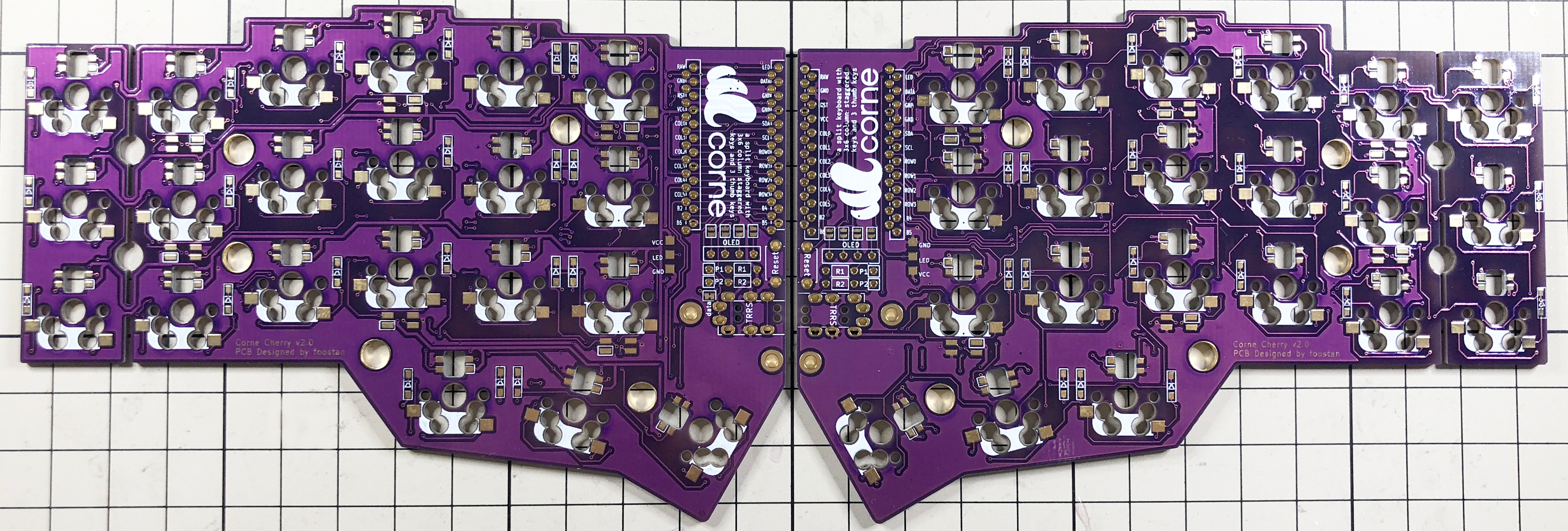
The PCB is reversible, so first decide which one to use,
|
|
|
|
|
left or right.
|
|
|
|
|
|
|
|
|
|
|
|
|
|
|
|
2021-05-15 08:52:32 +02:00
|
|
|
### Diodes
|
2021-04-17 15:22:45 +02:00
|
|
|
|
|
|
|
|
Solder the diode of the chip part.
|
|
|
|
|
You can attach it to either side, but in this build guide,
|
|
|
|
|
we will attach it to the back side.
|
|
|
|
|
When using [Tilting / Tenting plate](
|
|
|
|
|
https://github.com/foostan/crkbd/blob/master/corne-cherry/doc/buildguide_tilting_tenting_plate_en.md),
|
|
|
|
|
be sure to attach it to the back side \_\_.
|
|
|
|
|
|
|
|
|
|
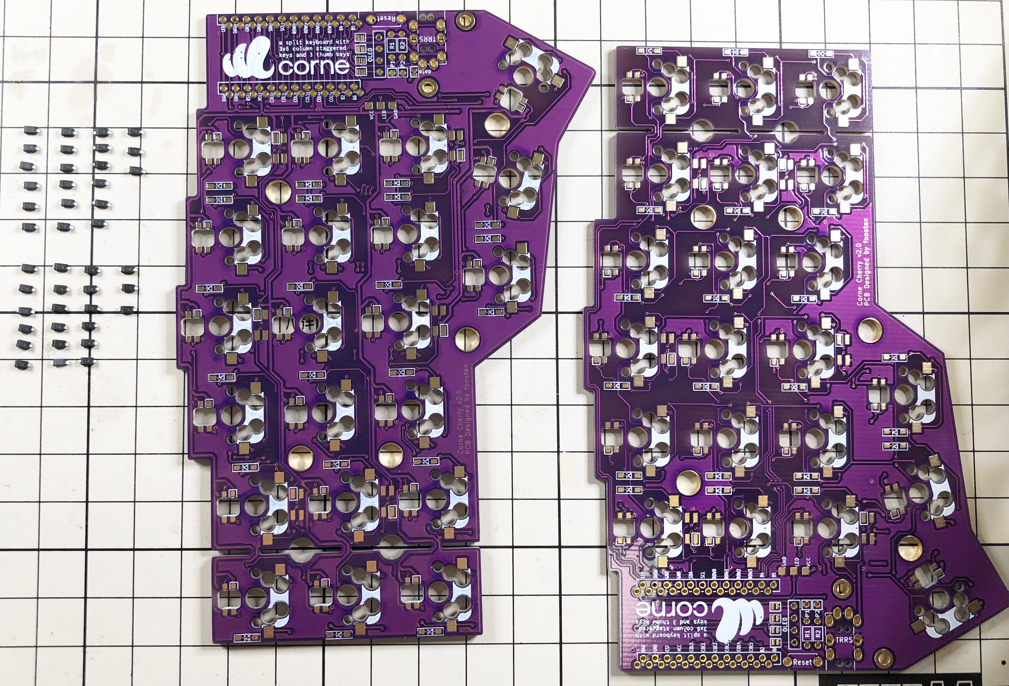
Since the chip parts are very small,
|
|
|
|
|
it is easier to work with tweezers and counter-acting tweezers.
|
|
|
|
|
**The diode is installed in a fixed direction **,
|
|
|
|
|
so if you arrange the diode in the same row and row as shown in the photo below,
|
|
|
|
|
it will proceed smoothly.
|
|
|
|
|
|
|
|
|
|
|
|
|
|
|
|
|
|
|
|
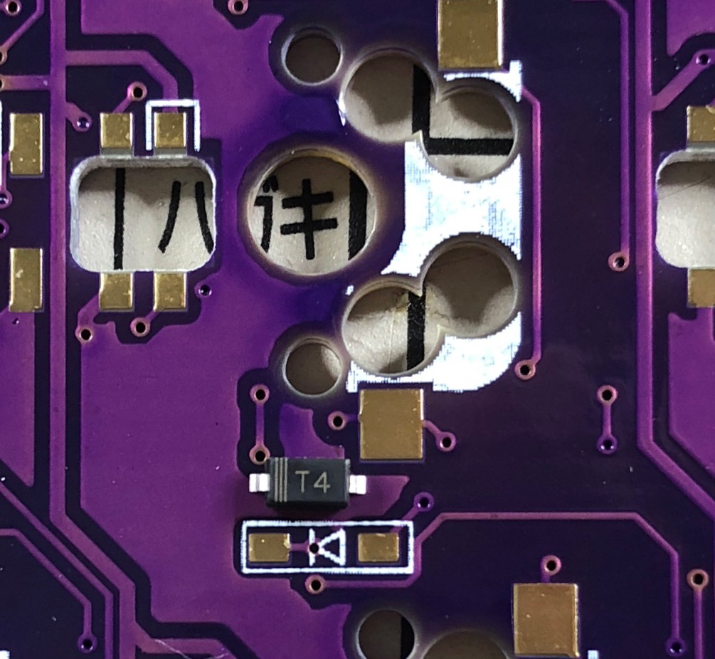
The orientation of the diode is as follows:
|
|
|
|
|
Install so that the "|||" mark on the chip part faces the "|" of the diode mark "|◁".
|
|
|
|
|
|
|
|
|
|
|
|
|
|
|
|
|
|
|
|
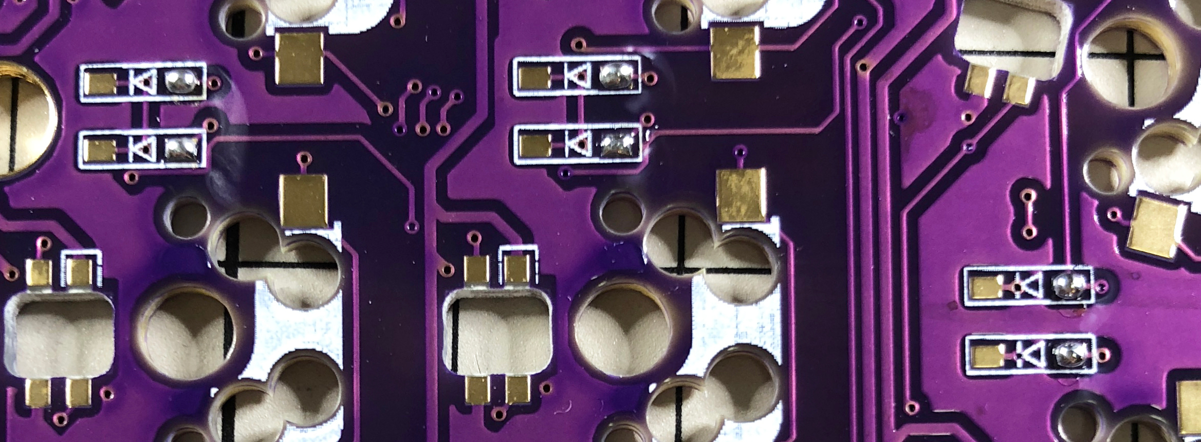
The trick is to attach the chip parts, but first, as a spare solder,
|
|
|
|
|
put the solder only on the right side of the pad.
|
|
|
|
|
|
|
|
|
|
|
|
|
|
|
|
|
|
|
|
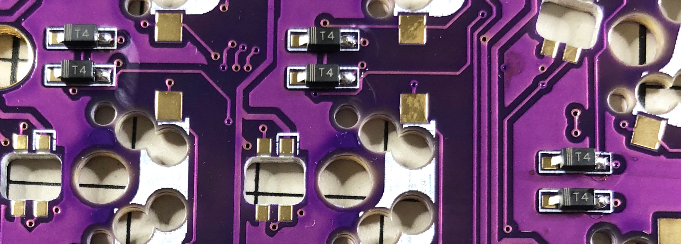
Next, solder one leg of the diode so that the spare solder melts.
|
|
|
|
|
At this time, it is recommended to use reverse-action tweezers,
|
|
|
|
|
because you can hold the chip parts firmly without exerting force
|
|
|
|
|
and you can concentrate on alignment and soldering.
|
|
|
|
|
Also, if the soldering iron is too hot or the solder is touched too much,
|
|
|
|
|
the flux contained in the solder may evaporate and form a clean pile of solder,
|
|
|
|
|
but it can be repaired later,
|
2021-05-15 11:20:11 +02:00
|
|
|
so at this point you should only care about attaching parts.
|
2021-04-17 15:22:45 +02:00
|
|
|
It's okay.
|
|
|
|
|
|
|
|
|
|
|
|
|
|
|
|
|
|
|
|
It is okay if the diode does not float when viewed from the side
|
|
|
|
|
when one foot is attached.
|
2021-05-15 11:20:11 +02:00
|
|
|
If it floats, press the diode with tweezers or your fingers
|
|
|
|
|
and reheat the soldered part with a soldering iron to clean it.
|
2021-04-17 15:22:45 +02:00
|
|
|
|
|
|
|
|

|
|
|
|
|
|
|
|
|
|
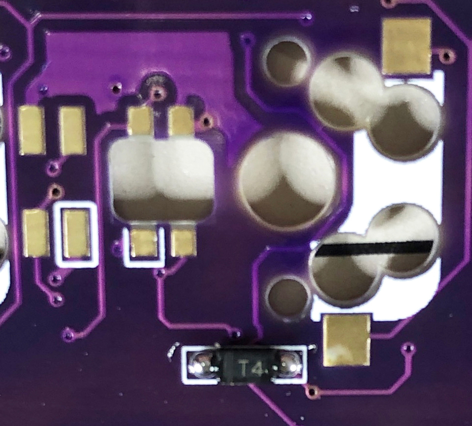
Then solder the other one.
|
2021-05-15 11:20:11 +02:00
|
|
|
Be careful not to apply too much,
|
|
|
|
|
as a small amount of solder is sufficient.
|
2021-04-17 15:22:45 +02:00
|
|
|
If you apply too much, you can remove it with a blotting wire
|
|
|
|
|
or by scooping it with a soldering iron.
|
|
|
|
|
|
|
|
|
|
If the amount of solder on the preliminary solder side is small,
|
|
|
|
|
additional soldering is performed, and if it is a mountain,
|
|
|
|
|
apply flux from above and heat it to clean it.
|
|
|
|
|
|
|
|
|
|
|
|
|
|
|
|
|
|
|
|
### TRRS jack, reset switch
|
|
|
|
|
|
|
|
|
|
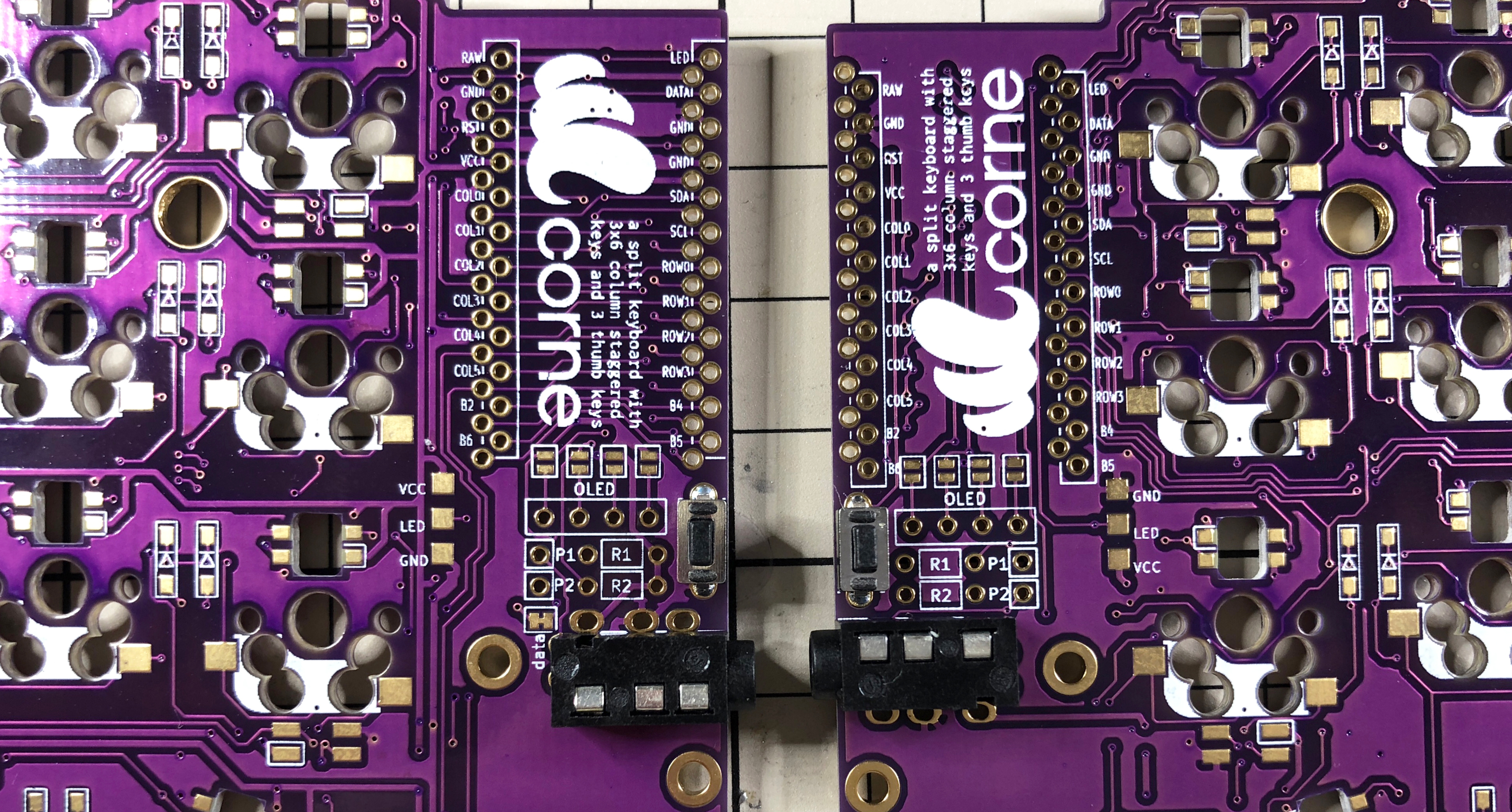
Solder the TRRS jack and reset switch to the surface of the PCB
|
|
|
|
|
as shown in the picture below.
|
|
|
|
|
In this build guide, the diode is attached to the back side,
|
|
|
|
|
so it is the opposite side.
|
|
|
|
|
|
|
|
|
|
|
|
|
|
|
|
|
|
|
|
### Jumpers and pin sockets for OLED modules
|
|
|
|
|
|
|
|
|
|
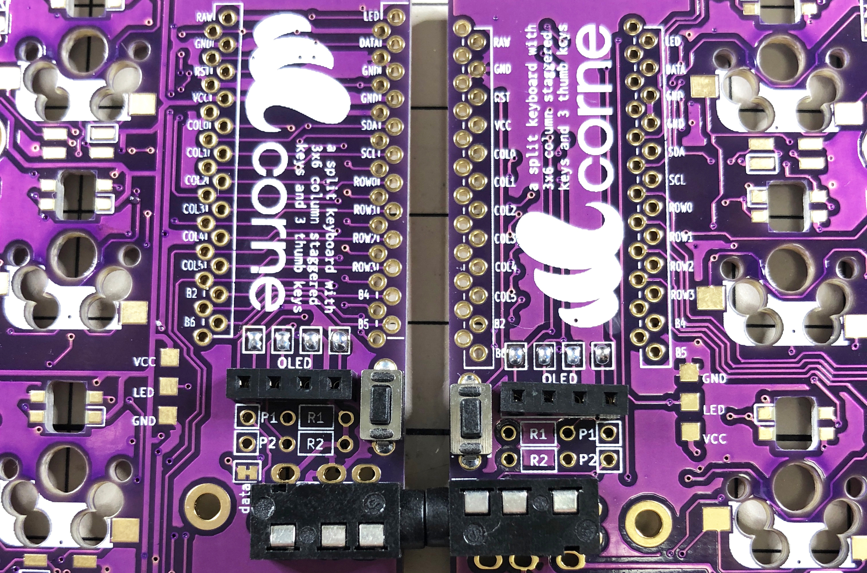
When using the OLED module, jumper as shown below.
|
|
|
|
|
Please note that **only the surface should be jumpered**.
|
|
|
|
|
|
|
|
|
|
Solder the pin socket to the same surface.
|
|
|
|
|
|
|
|
|
|
|
|
|
|
|
|
|
|
|
|
If the jumper doesn't work, the amount of solder is probably too low
|
|
|
|
|
or the flux in the solder has vaporized.
|
|
|
|
|
In that case, you can fix a jumper by using a large amount of solder
|
|
|
|
|
or applying a separate flux.
|
|
|
|
|
|
|
|
|
|
### ProMicro
|
|
|
|
|
|
|
|
|
|
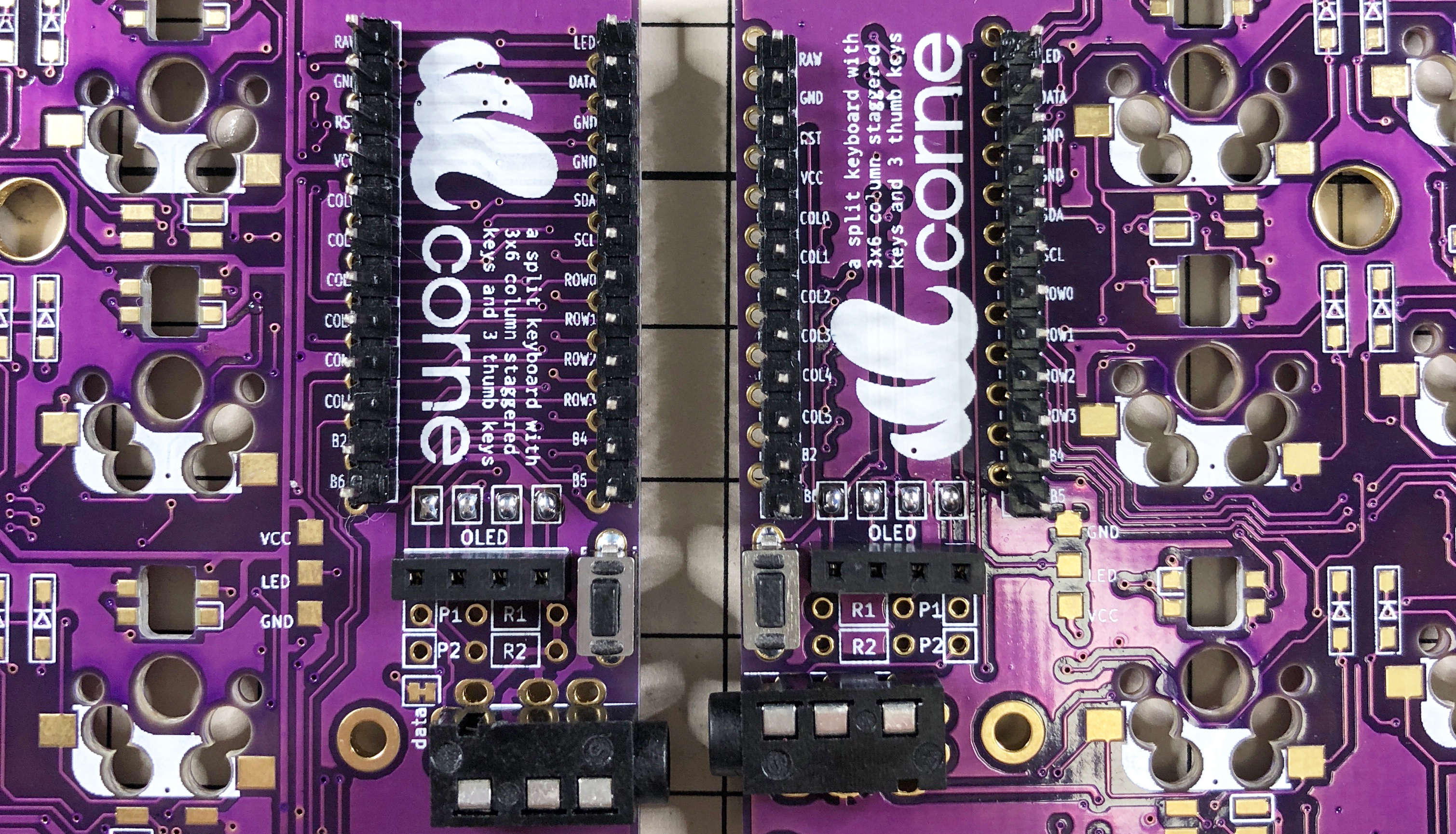
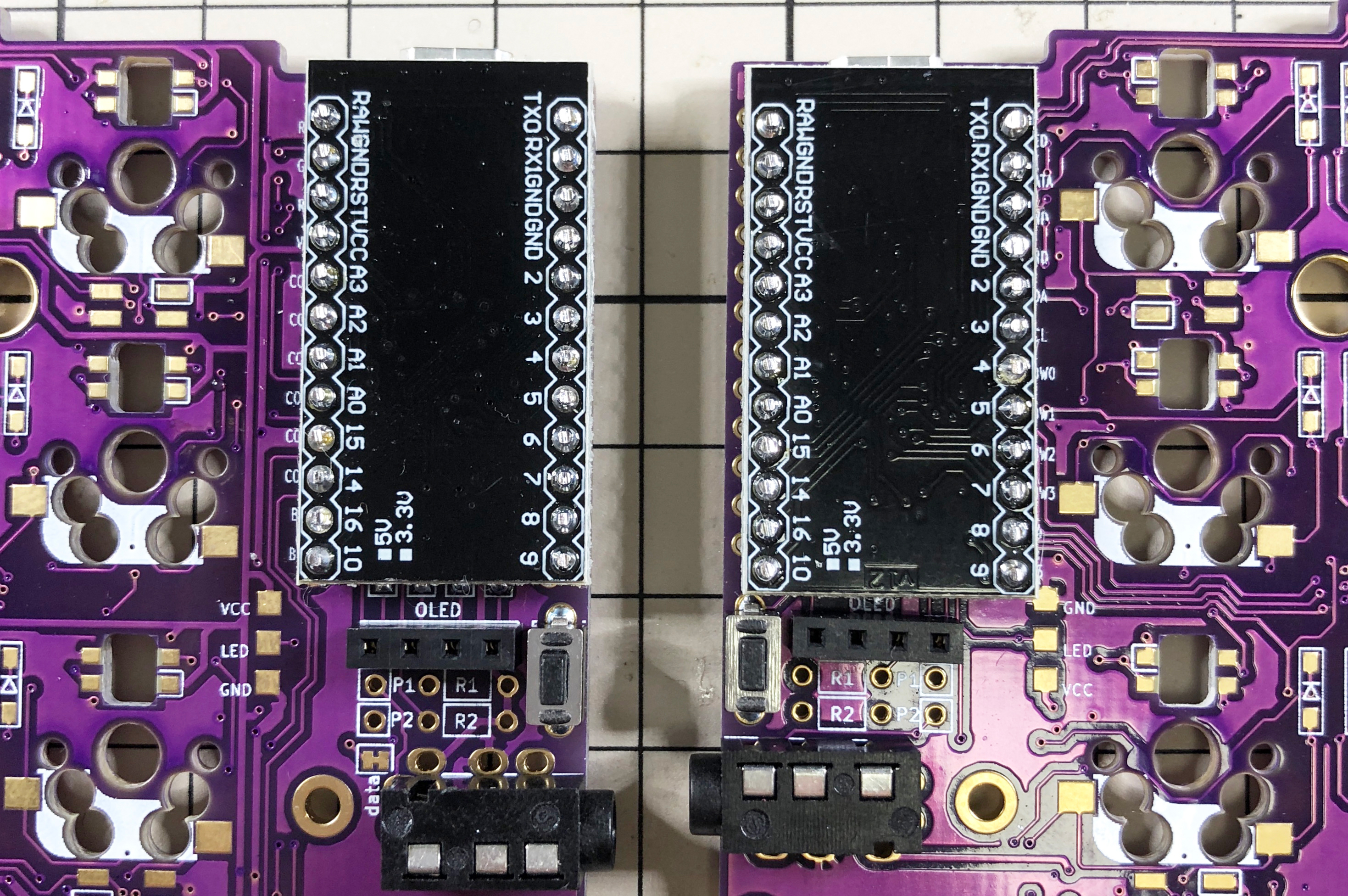
Solder the pin header so that it fits into the white frame,
|
|
|
|
|
and then solder it with the back side of the Pro Micro facing up.
|
|
|
|
|
|
|
|
|
|
|
|
|
|
|
|
|
|
|
|
|
2021-05-15 11:20:11 +02:00
|
|
|
If you want to use spring-loaded pin headers,
|
|
|
|
|
please refer to the [Helix Build Guide](
|
2021-04-17 15:22:45 +02:00
|
|
|
https://github.com/MakotoKurauchi/helix/blob/master/Doc/buildguide_en.md#pro-micro).
|
|
|
|
|
|
|
|
|
|
### OLED module
|
|
|
|
|
|
|
|
|
|
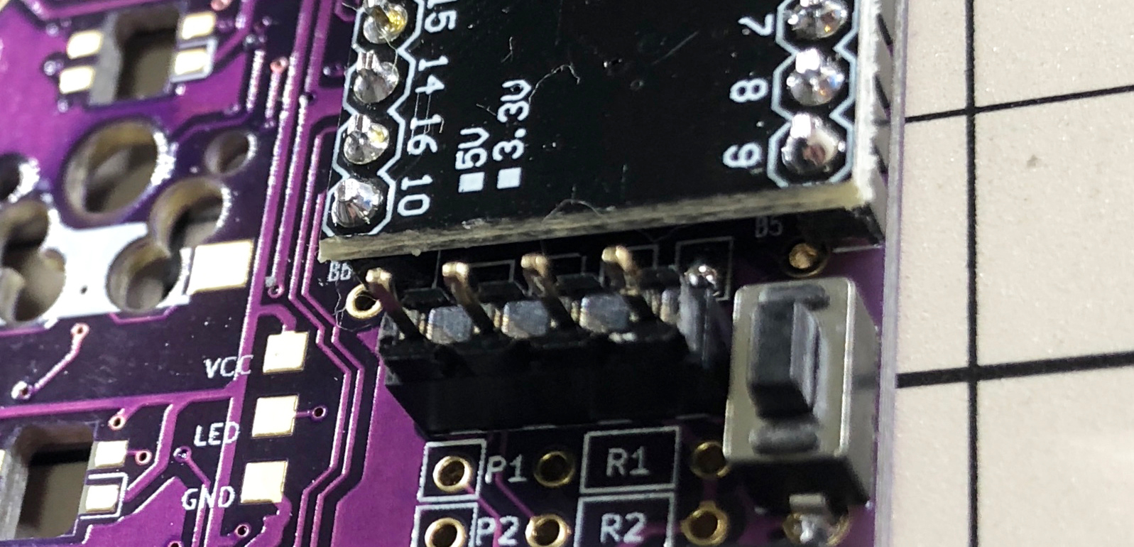
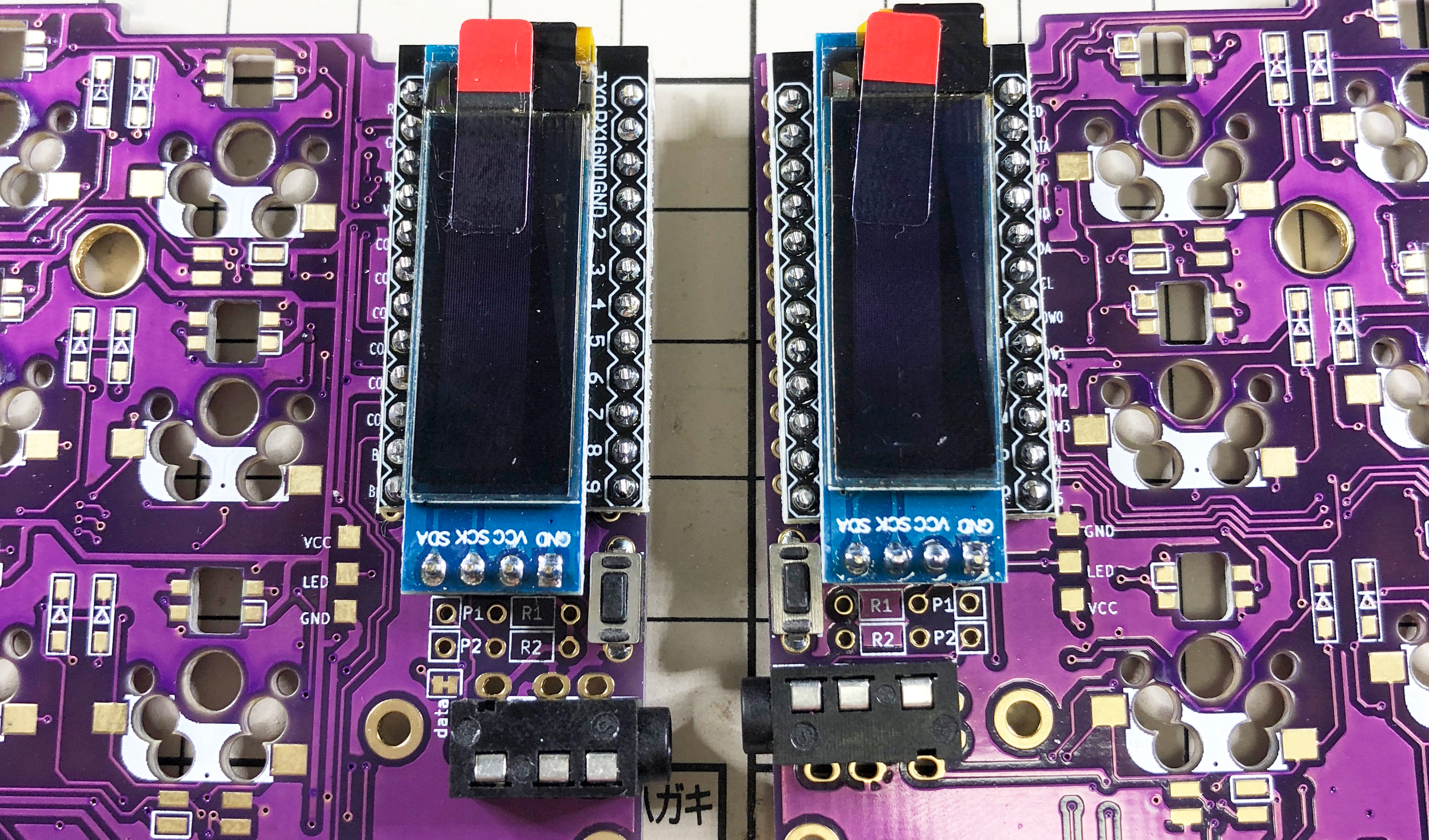
Insert the pin header into the pin socket for OLED first,
|
|
|
|
|
and then solder the pin header and OLED module.
|
|
|
|
|
At this time, the OLED module is easy to float,
|
|
|
|
|
so be careful not to float it while pressing it with your finger.
|
|
|
|
|
|
|
|
|
|
|
|
|
|
|
|
|
|
|
|
|
|
|
|
|
### Operation check
|
|
|
|
|
|
|
|
|
|
It is recommended to check the operation when ProMicro and OLED module are attached
|
|
|
|
|
(it will be difficult to isolate the problem if you do it at the very end).
|
|
|
|
|
|
|
|
|
|
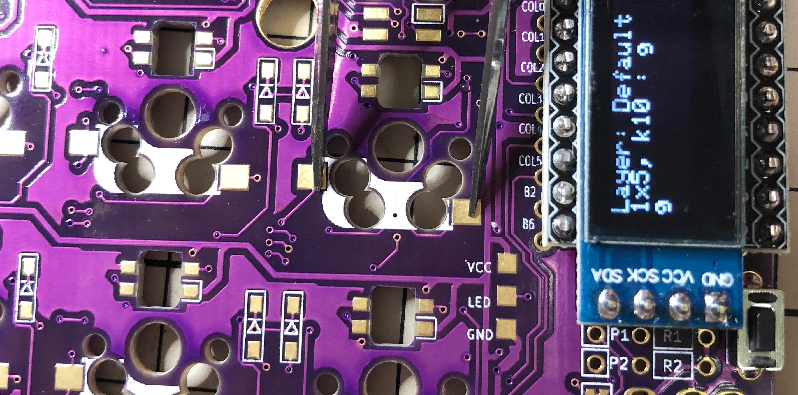
To check the operation, first insert the firmware for crkbd into ProMicro
|
|
|
|
|
by referring to the "Firmware" chapter below (be sure to insert it on both sides).
|
|
|
|
|
|
2021-05-15 11:20:11 +02:00
|
|
|
To check the operation,
|
|
|
|
|
connect the left hand side to the PC with MicroUSB,
|
2021-04-17 15:22:45 +02:00
|
|
|
and connect the left hand side and the right hand side with the TRS cable.
|
|
|
|
|
Since there may be defects such as jacks,
|
2021-05-15 11:20:11 +02:00
|
|
|
be sure to connect the left and right instead of one by one
|
|
|
|
|
before checking the operation.
|
2021-04-17 15:22:45 +02:00
|
|
|
If it is done correctly so far,
|
|
|
|
|
if you short the pad to attach the PCB socket with tweezers etc.,
|
|
|
|
|
the key pressed on the OLED module will be displayed.
|
|
|
|
|
|
|
|
|
|
|
|
|
|
|
|
|
|
|
|
### Kailh PCB Socket
|
|
|
|
|
|
|
|
|
|
Fill the pads on both sides of the back with solder.
|
|
|
|
|
It is difficult to add it later, so please add more in advance.
|
|
|
|
|
|
|
|
|
|

|
|
|
|
|
|
|
|
|
|
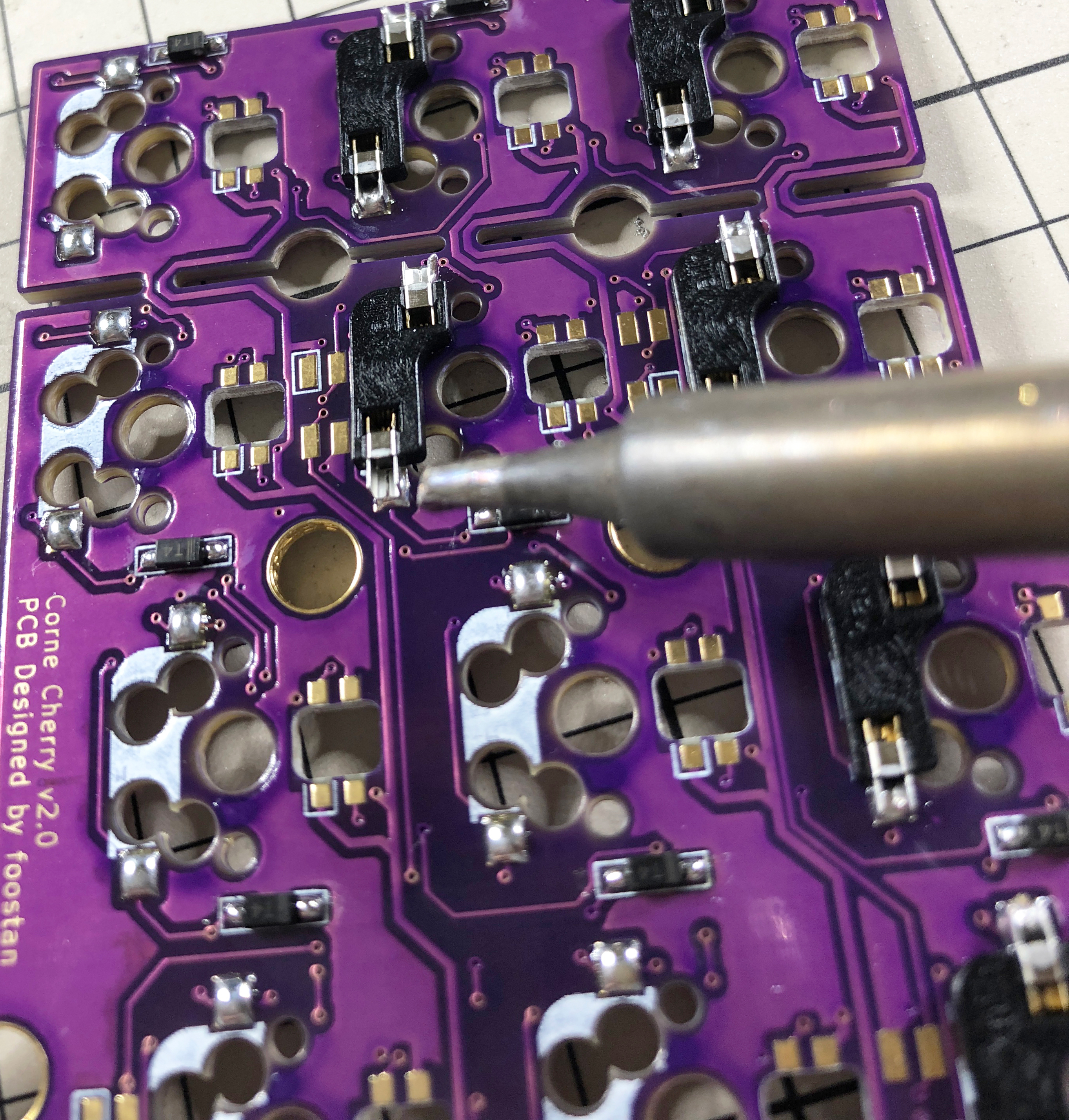
Insert the socket and attach it by melting the solder you have.
|
|
|
|
|
At this time, hold it down with tweezers or your fingers
|
|
|
|
|
so that the socket does not float.
|
|
|
|
|
|
|
|
|
|
|
|
|
|
|
|
|
|
|
|
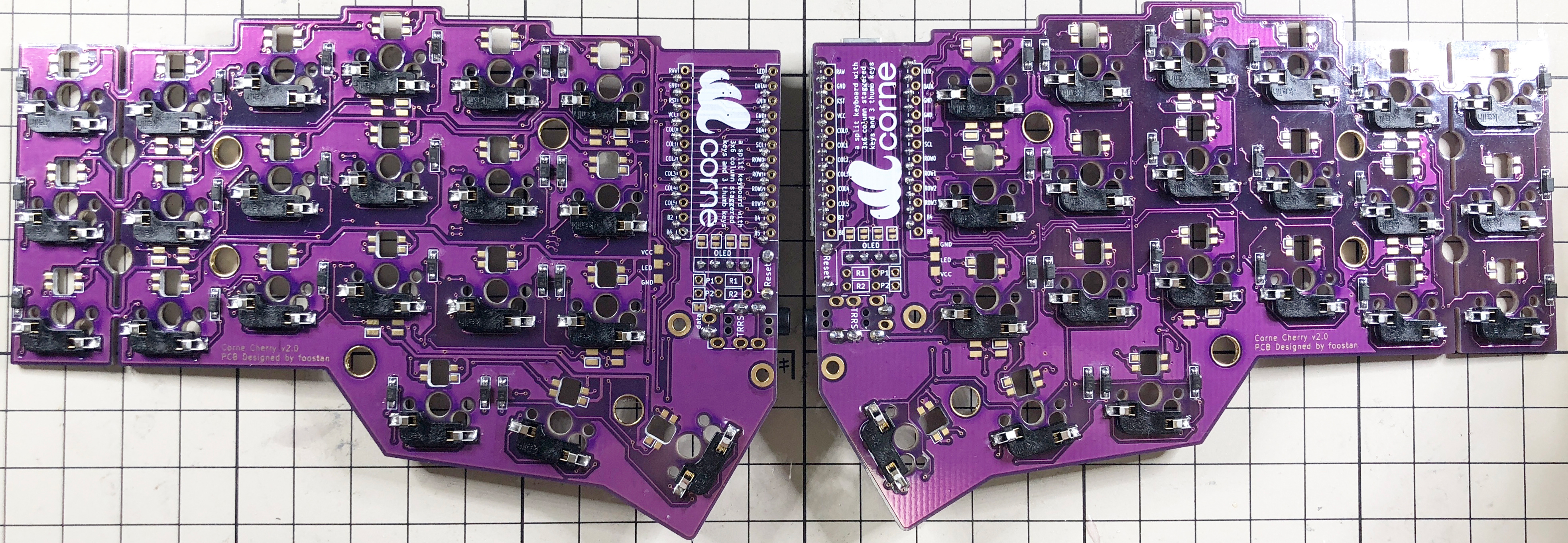
Soldering is now complete.
|
|
|
|
|
If you want to add an LED as an option,
|
|
|
|
|
refer to the "LED" chapter below
|
|
|
|
|
(it can be attached even after installing the socket).
|
|
|
|
|
|
|
|
|
|
|
|
|
|
|
|
|
|
|
|
### Plates, switches
|
|
|
|
|
|
|
|
|
|
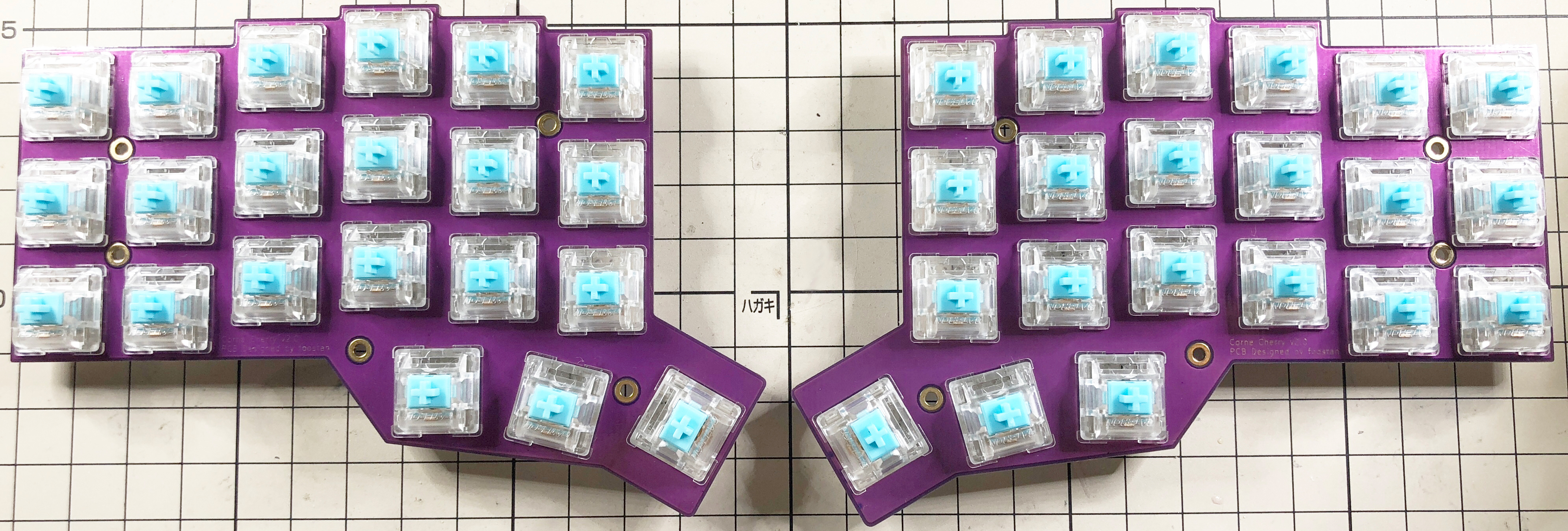
First, insert the switch into the top plate.
|
|
|
|
|
It's okay to do it later, but it's easier to put it in first,
|
|
|
|
|
because it's necessary to insert the switch from a little bit.
|
|
|
|
|
|
|
|
|
|
|
|
|
|
|
|
|
|
|
|
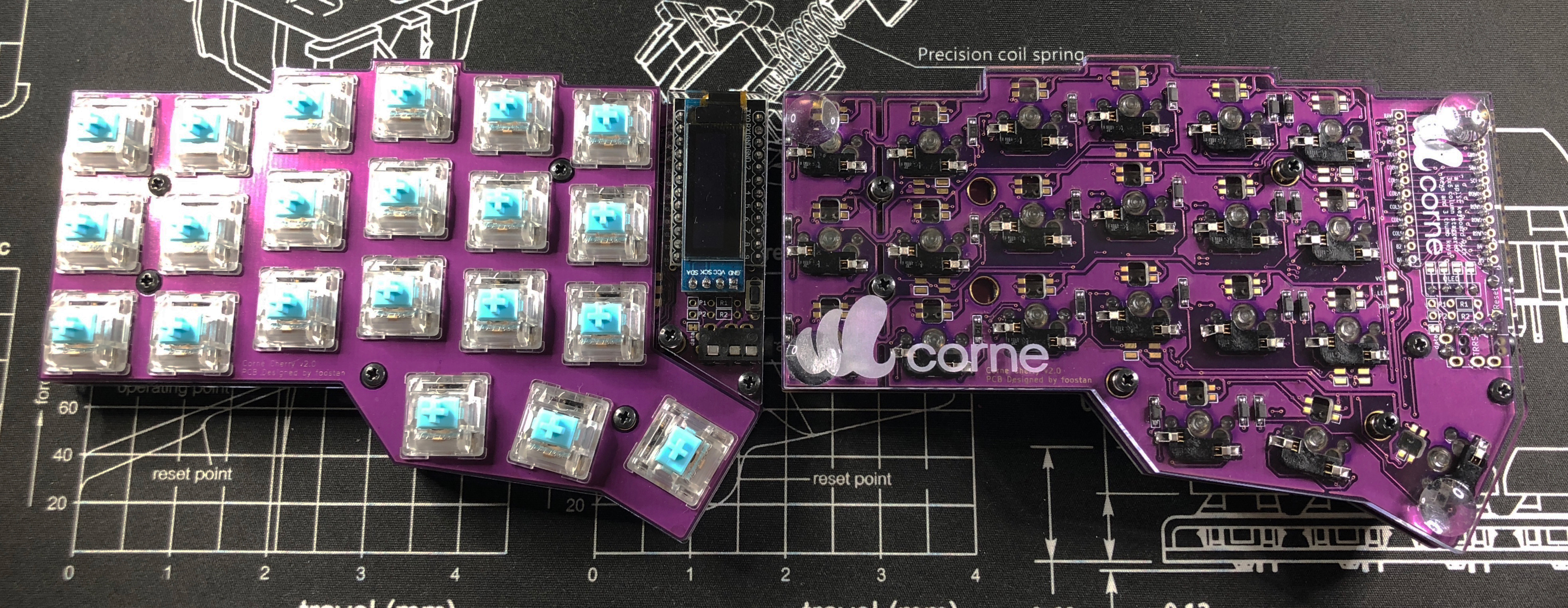
Finally, attach the spacers with screws so that the top plate, PCB,
|
|
|
|
|
and bottom plate are in that order,
|
|
|
|
|
and attach the cushion rubber to the four corners to complete the process.
|
|
|
|
|
|
|
|
|
|
|
|
|
|
|
|
|
|
|
|
## Firmware
|
|
|
|
|
|
|
|
|
|
Write the firmware to ProMicro by referring to the following. \
|
|
|
|
|
<https://github.com/foostan/crkbd/blob/master/doc/firmware_en.md>
|
|
|
|
|
|
|
|
|
|
## LED (optional)
|
|
|
|
|
|
|
|
|
|
I will install the SK6812 MINI.
|
|
|
|
|
|
|
|
|
|
The SK6812MINI is extremely heat sensitive and breaks easily.
|
|
|
|
|
We recommend using a soldering iron with a temperature control function
|
|
|
|
|
and working at a temperature of 220°C to 270°C.
|
|
|
|
|
Even if the temperature is adjusted,
|
|
|
|
|
it will be damaged if the iron is applied to the LED for a long time,
|
|
|
|
|
so try to solder as quickly as possible.
|
|
|
|
|
The LEDs are soldered four by four,
|
|
|
|
|
but it is recommended that you do not do four at a time,
|
|
|
|
|
but two at a time to prevent the LED temperature from rising,
|
|
|
|
|
as it will be less likely to break.
|
|
|
|
|
|
|
|
|
|
First, check the mounting position.
|
|
|
|
|
|
|
|
|
|
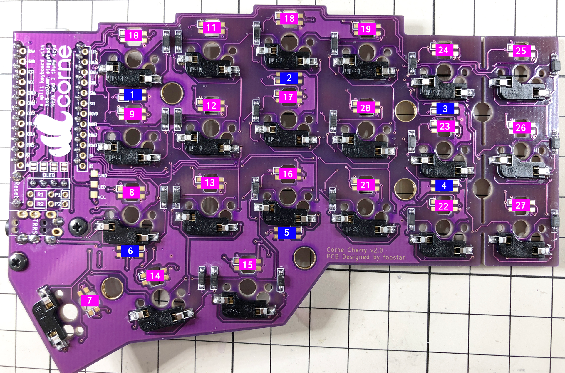
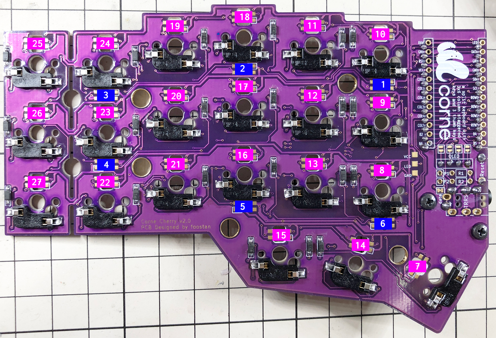
Solder 1 to 6 so that the back side (Undergrow) shines,
|
|
|
|
|
and 7 to 27 so that the front side (Backlight) shines.
|
|
|
|
|
Below is the position to install the LED.
|
|
|
|
|
|
|
|
|
|
|
|
|
|
|
|
|
|
|
|
|
|
|
|
|
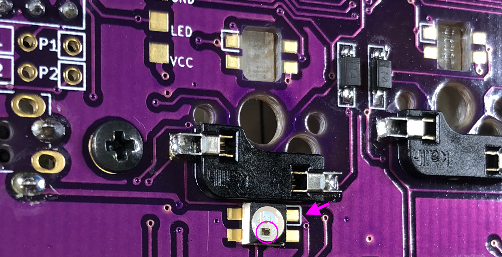
Solder 1 to 6 so that the black part circled as shown below is on the bottom
|
|
|
|
|
and the silk mark indicated by the arrow is on the top.
|
|
|
|
|
Please note that the orientation changes between 1 ~ 3 and 4 ~ 5.
|
|
|
|
|
|
|
|
|
|
|
|
|
|
|
|
|
|
|
|
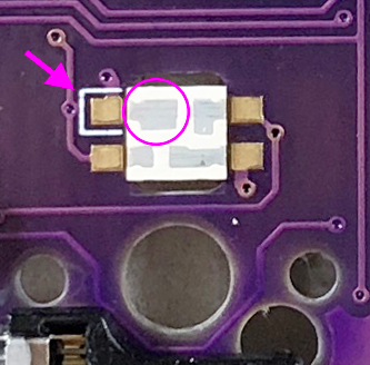
Solder 7 to 27 so that the largest pad circled
|
|
|
|
|
and the silk mark indicated by the arrow are adjacent to each other,
|
|
|
|
|
as shown below.
|
|
|
|
|
|
|
|
|
|
|
|
|
|
|
|
|
|
|
|
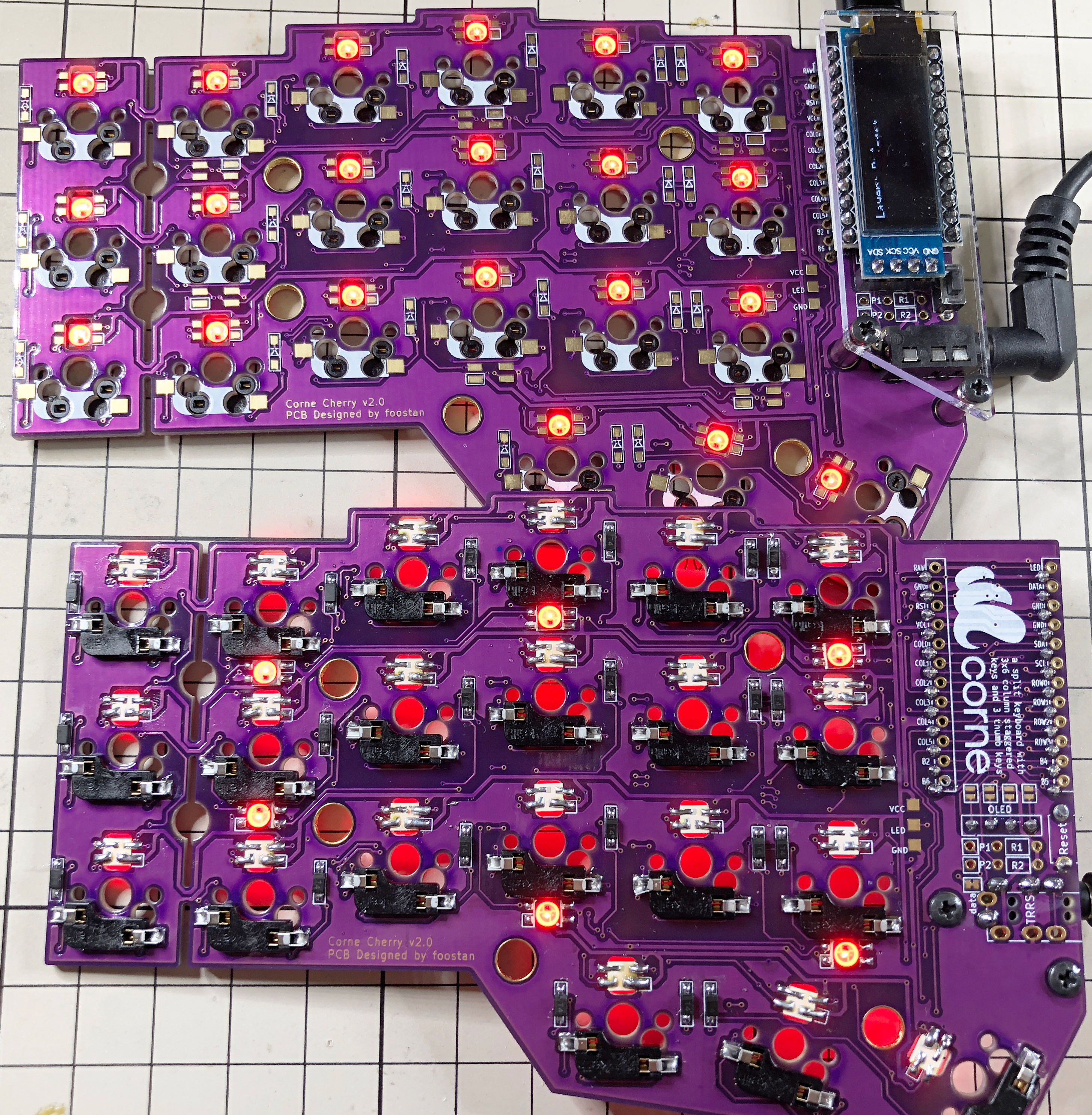
If everything can be soldered normally, it will shine as shown below.
|
|
|
|
|
If it shines only halfway, the LEDs are connected in numerical order,
|
|
|
|
|
so suspect that the LED that does not shine
|
|
|
|
|
or the LED in front of it is soldered incorrectly or that the LED is damaged.
|
|
|
|
|
|
|
|
|
|
|
|
|
|
|
|
|
|
|
|
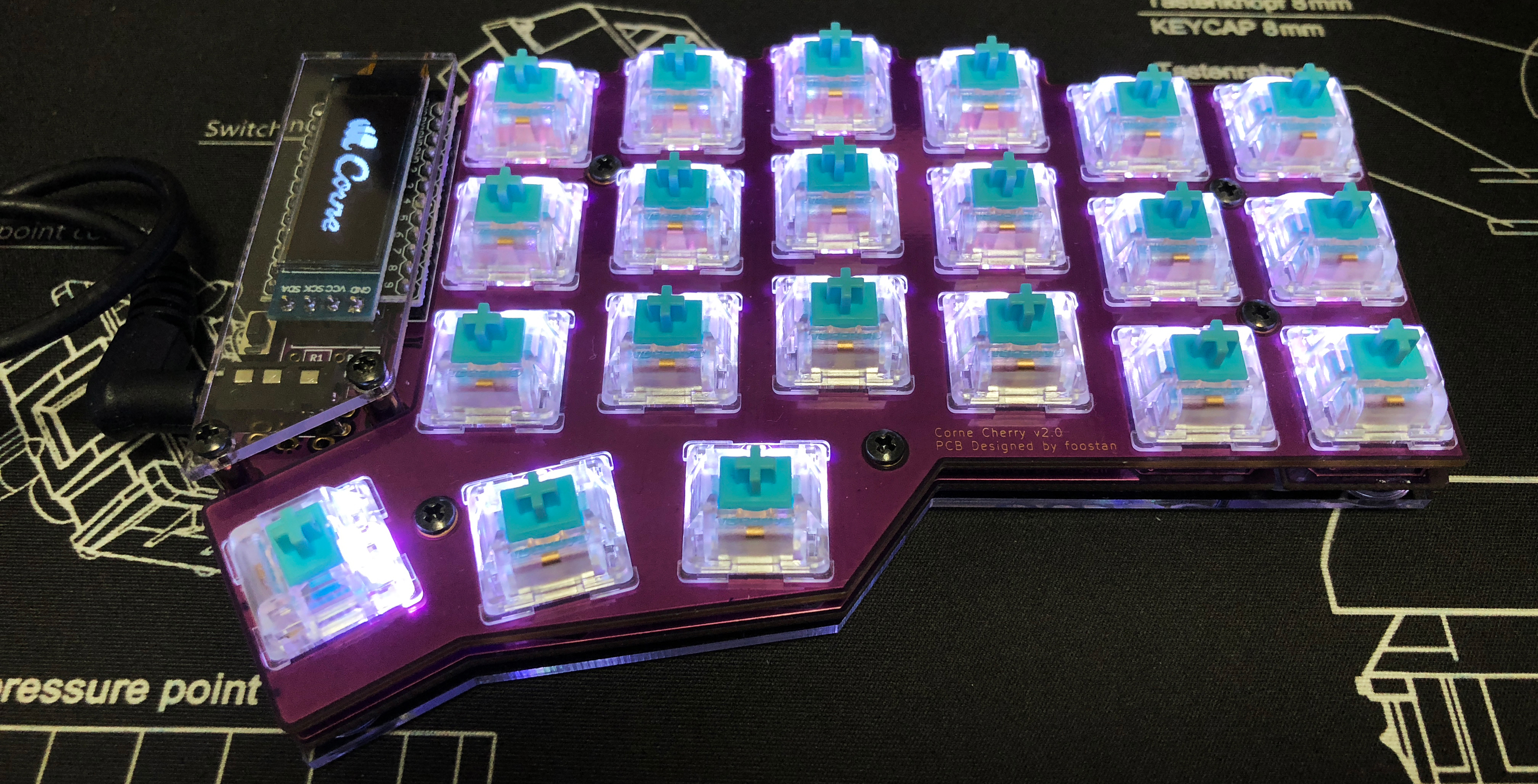
That's all there is to it.
|
|
|
|
|
|
|
|
|
|
|