| 名前 | 数 | 備考 |
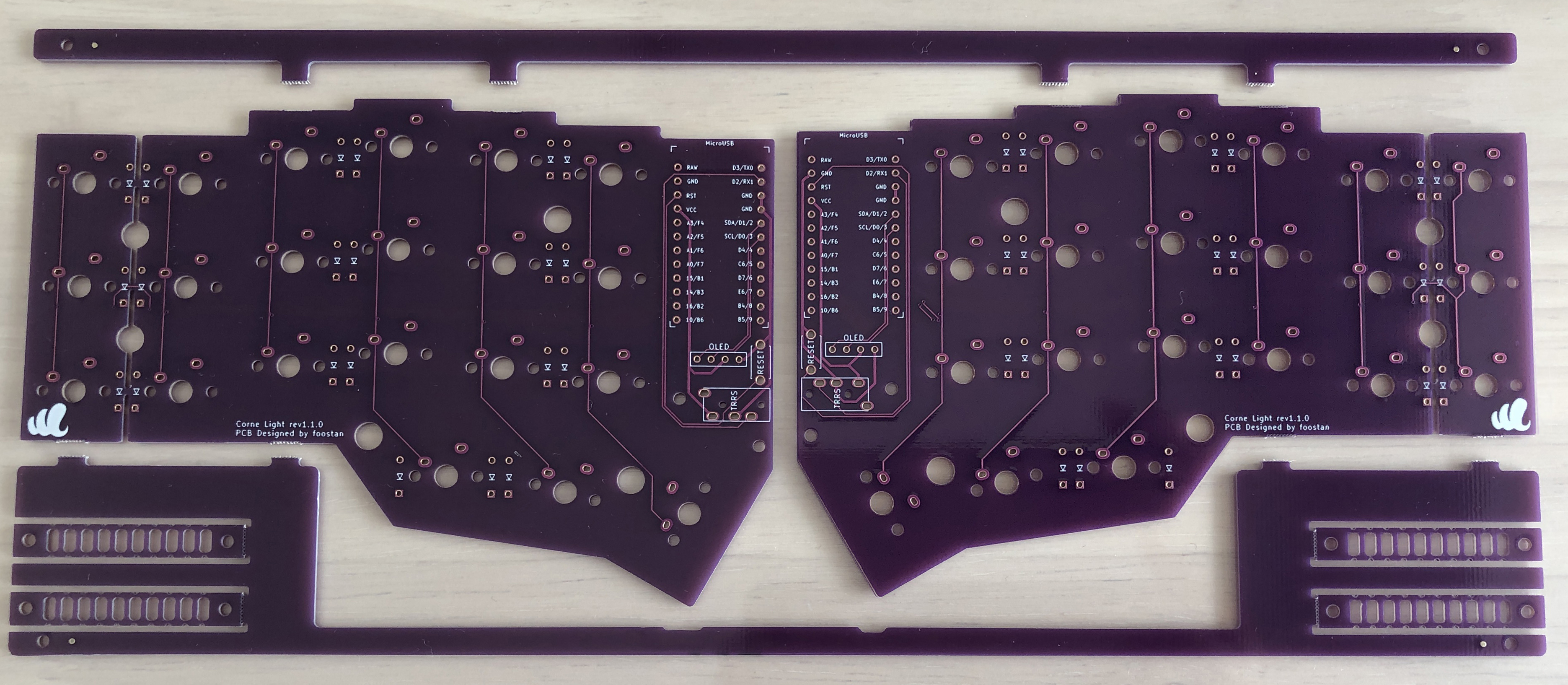
| PCB | 1セット |
|
| トッププレート | 2枚 |
|
| ボトムプレート | 2枚 |
|
| ProMicro保護プレート | 2枚 | |
| ダイオード | 42本 |
|
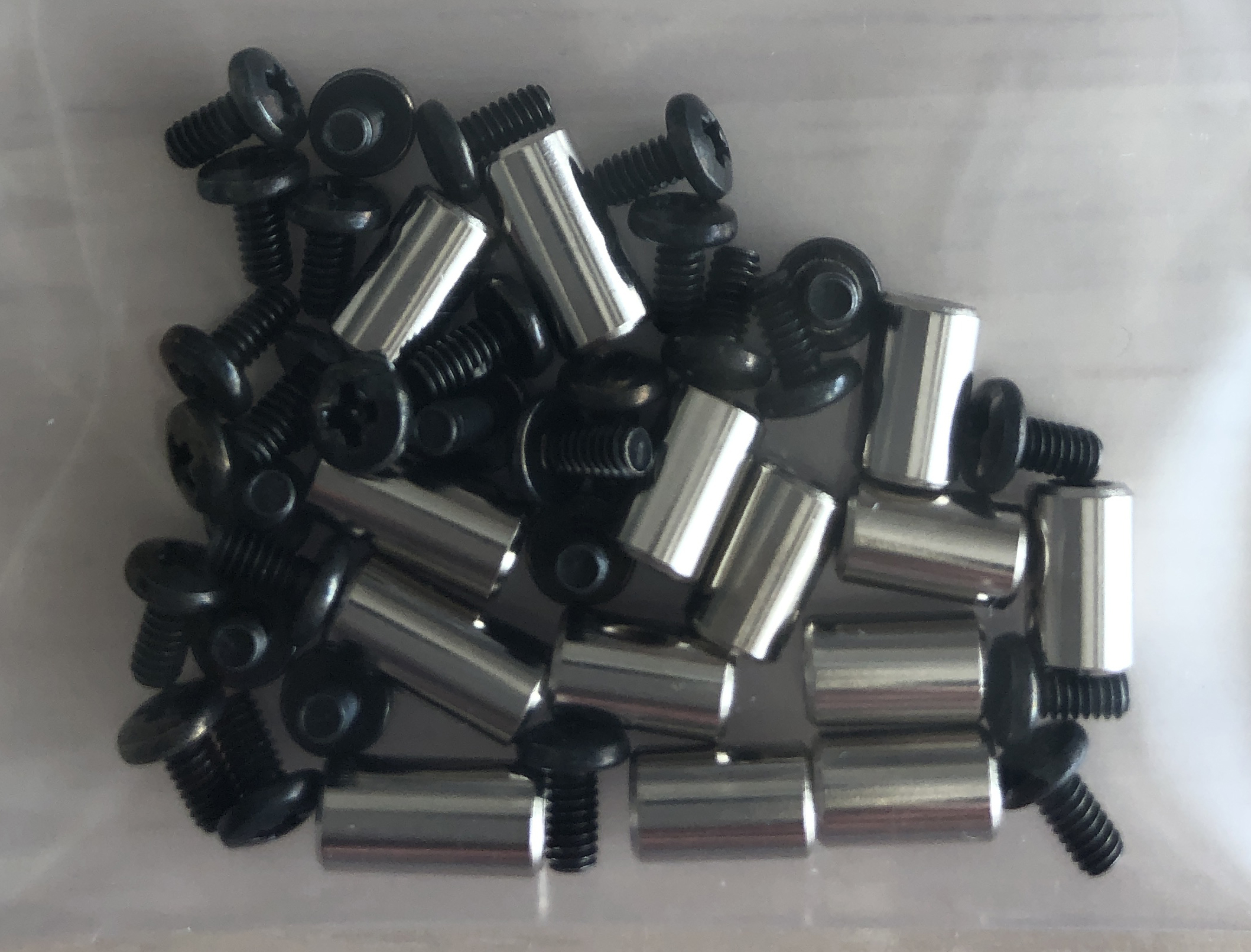
| スペーサー M2 7.5mm | 10本 |
|
| スペーサー M2 9mm | 4本 | |
| ネジ M2 4mm | 28本 | |
| TRRSジャック | 2つ |
|
| リセットスイッチ | 2つ | |
| ゴム足 | 8つ | |
| ProMicro(コンスルー付き) | 2つ | https://yushakobo.jp/shop/promicro-spring-pinheader/ |
| OLEDモジュール(ピンソケット付き) | 2つ | https://yushakobo.jp/shop/oled/ |
| キースイッチ | 42個 | |
| キーキャップ | 42個 | |
| TRRSケーブル | 1本 | TRSケーブルでも可 |
| USBケーブル | 1本 |
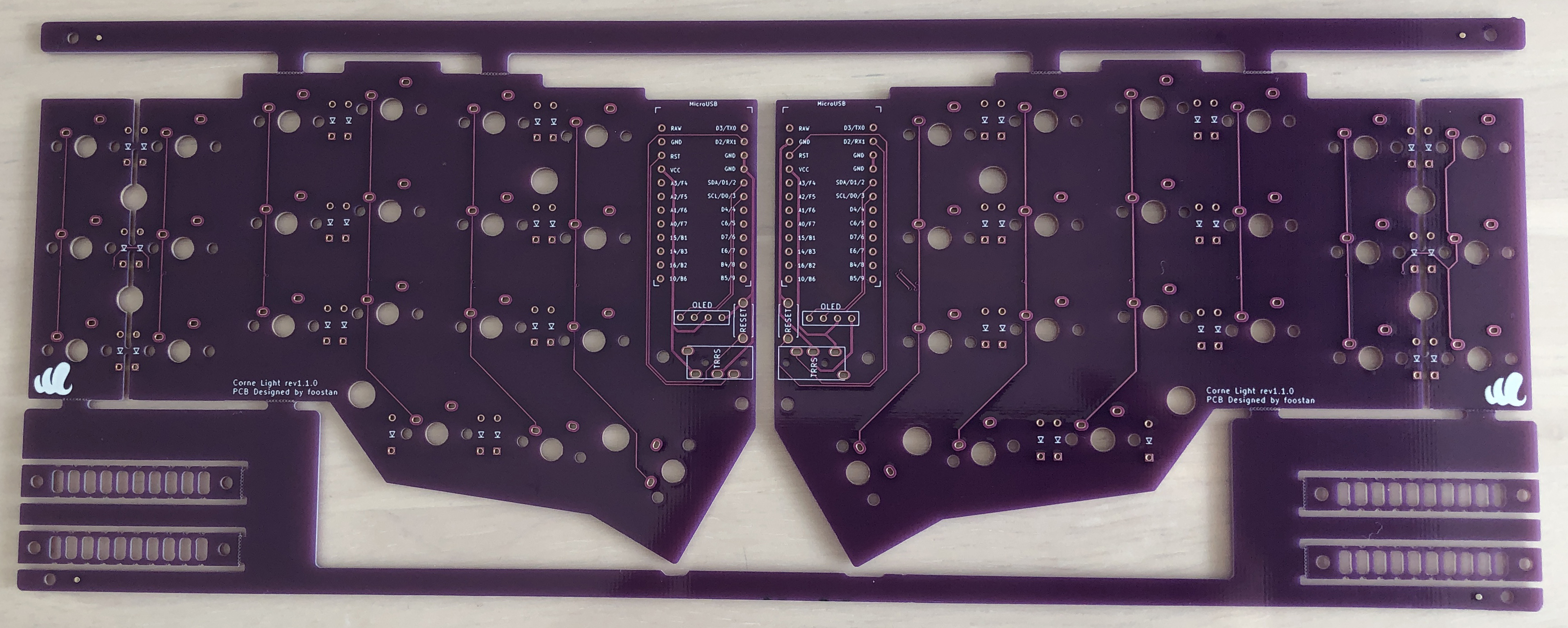
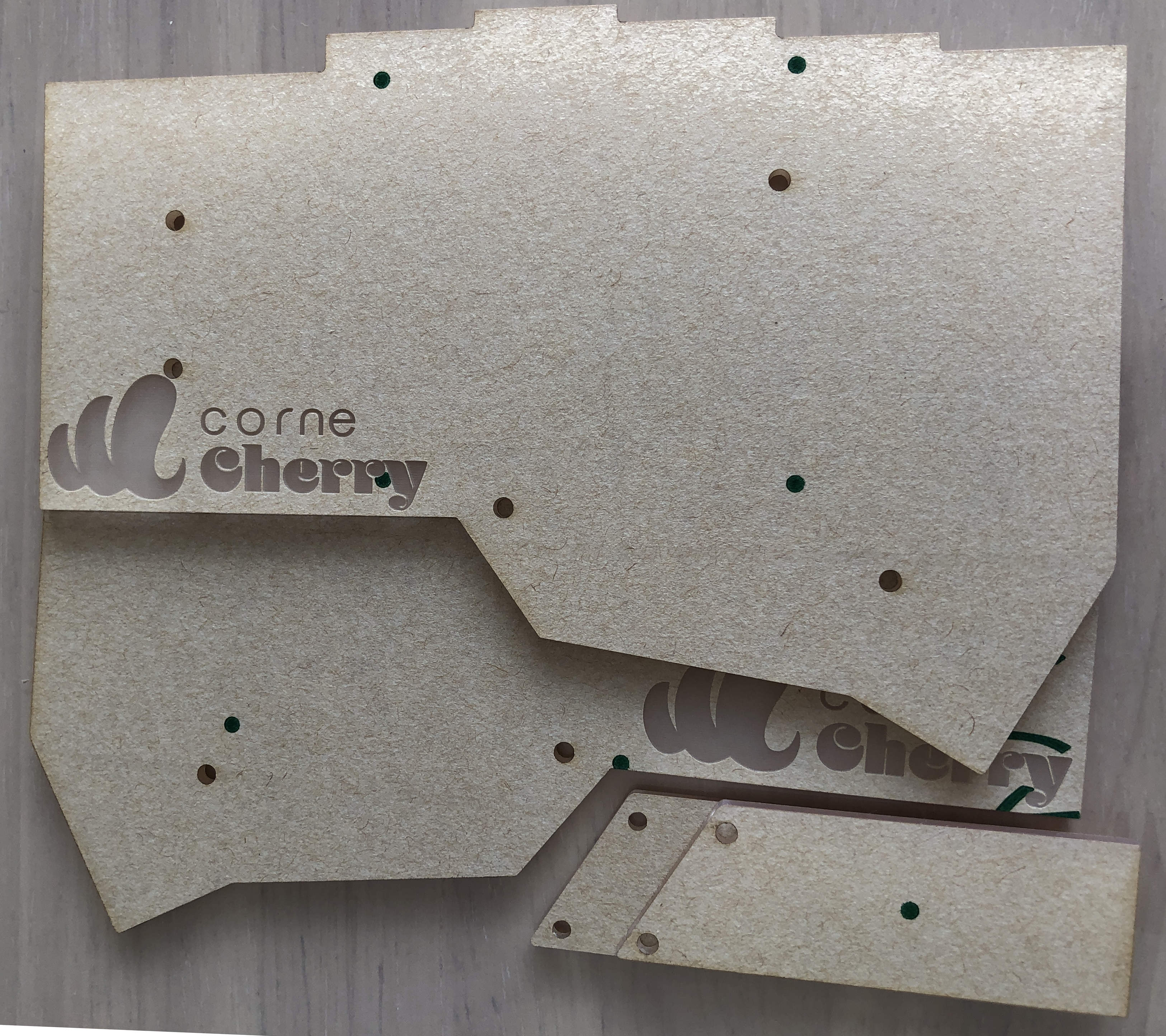
 こちらはダイオードの足を曲げるための治具です。
必要に応じて切り離しておきます。
こちらはダイオードの足を曲げるための治具です。
必要に応じて切り離しておきます。
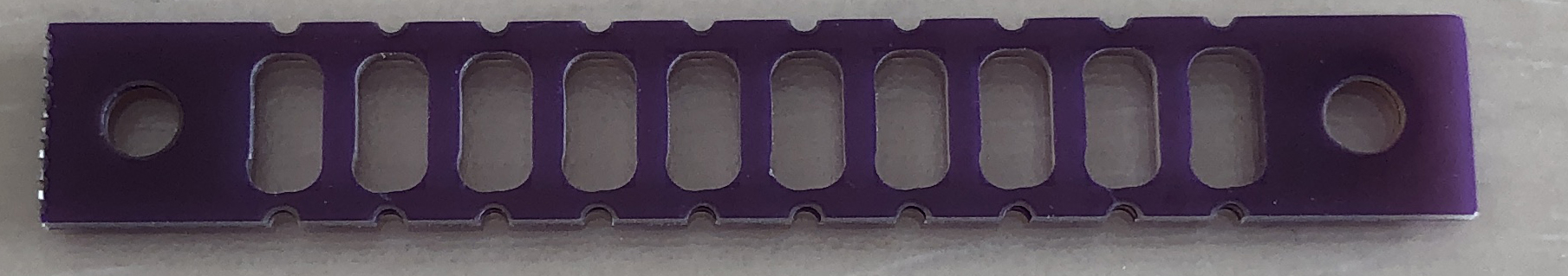 ※ バージョンによって治具が付いていないものもあります。
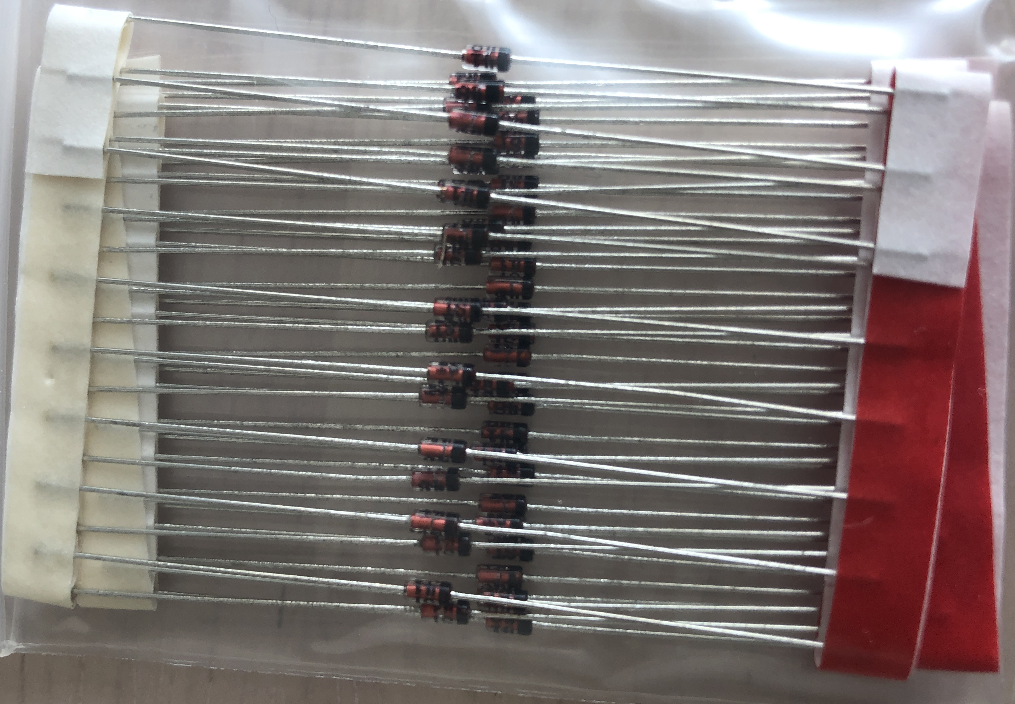
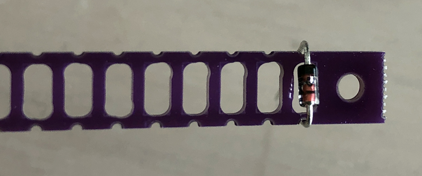
### ダイオード
まずはリードタイプのダイオードの足を曲げていきます。
※ 写真のように一本ずつ曲げるときれいにできますが、テープに繋がれたまま複数本を同時に曲げたほうが効率的です。
※ バージョンによって治具が付いていないものもあります。
### ダイオード
まずはリードタイプのダイオードの足を曲げていきます。
※ 写真のように一本ずつ曲げるときれいにできますが、テープに繋がれたまま複数本を同時に曲げたほうが効率的です。
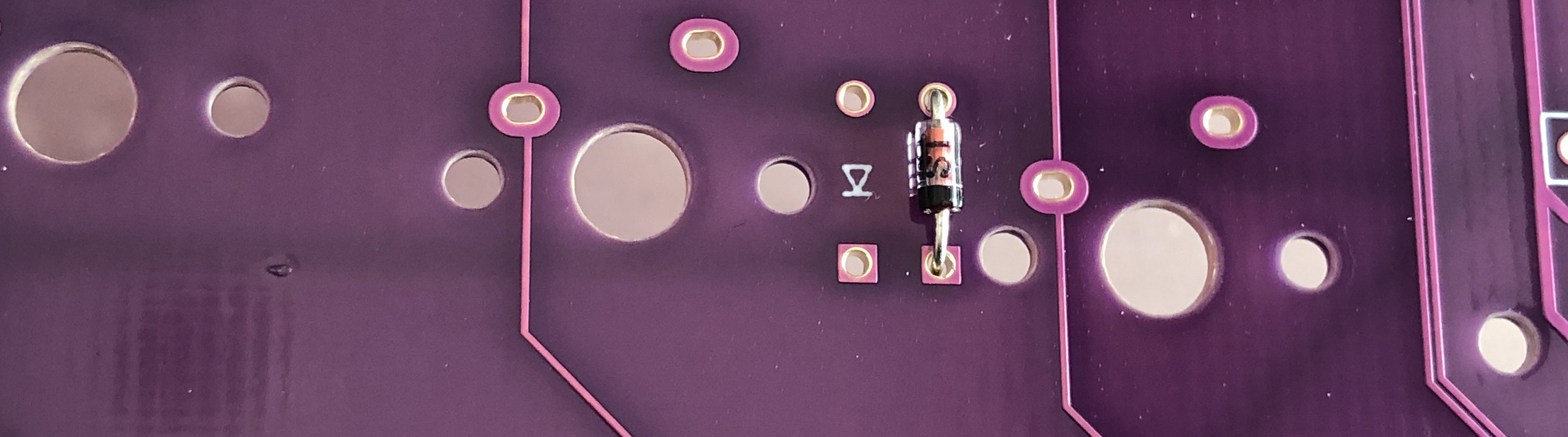
 足を曲げたダイオードを指定の位置に付けていきます。
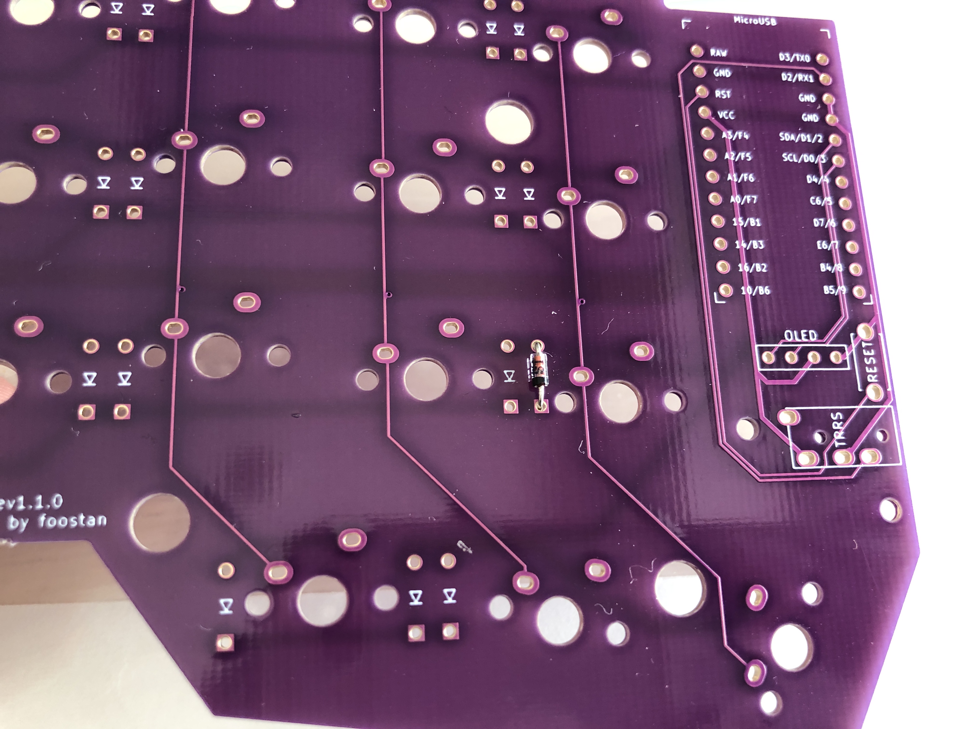 ダイオードには向きがあり、写真のように取り付けます。
※ 取り付けるダイオードはすべて同じ向きです。
ダイオードには向きがあり、写真のように取り付けます。
※ 取り付けるダイオードはすべて同じ向きです。
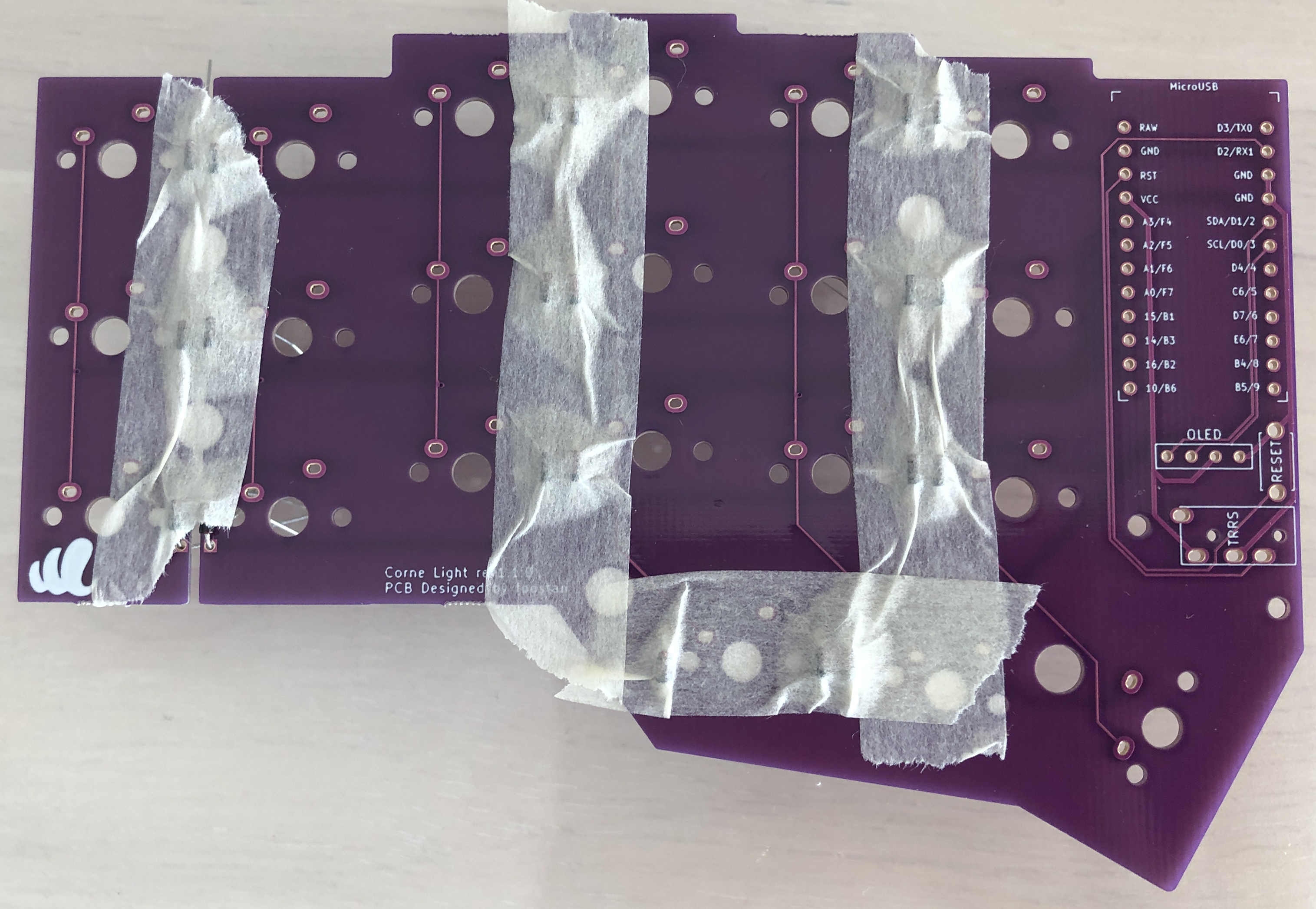
 マスキングテープで固定するときれいに付けることができます。
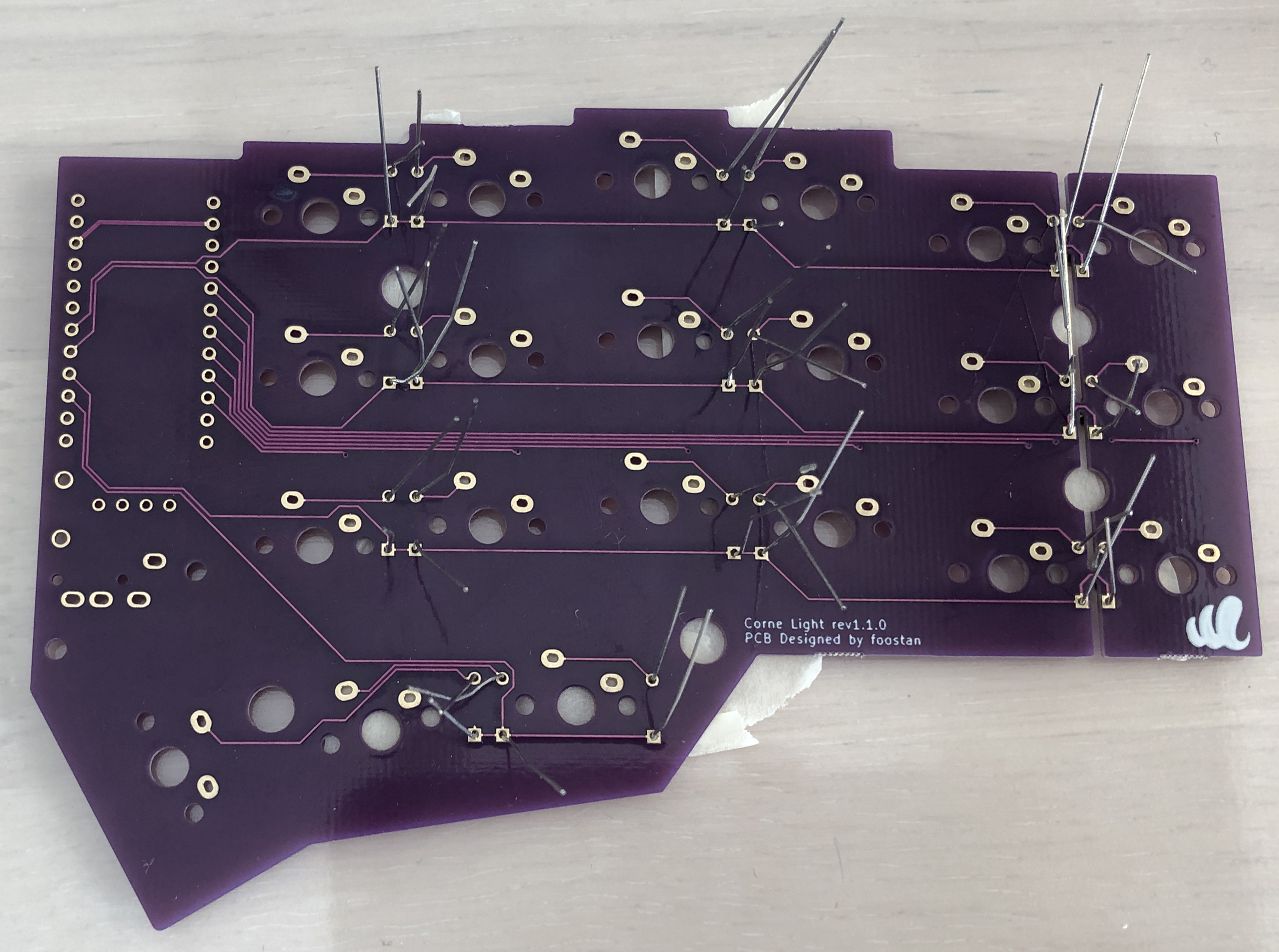
 裏面からはんだ付けを行います。
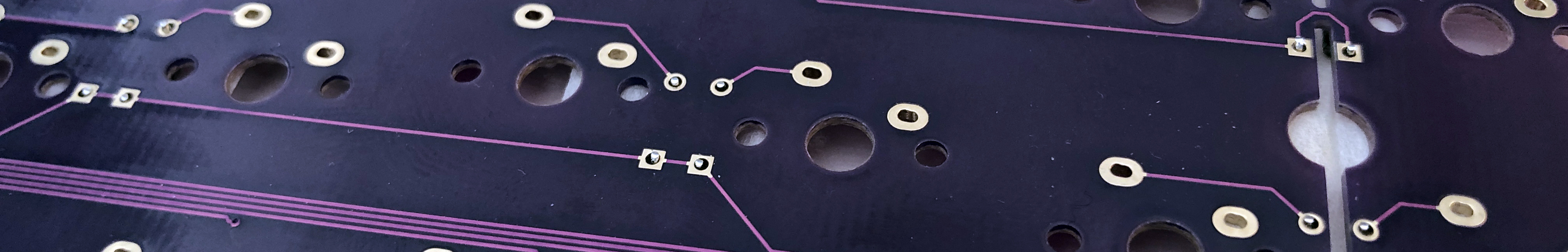
 マスキングテープで固定している場合はこのようにギリギリまで足を切るとはんだ付けがやりやすくなります。
 片手21個、両手分で 42 個のダイオードを取り付けます。
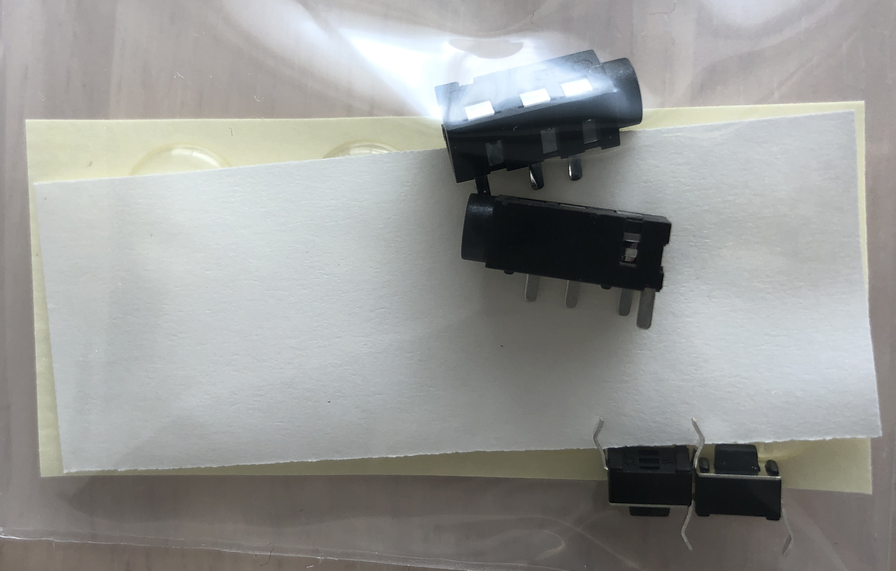
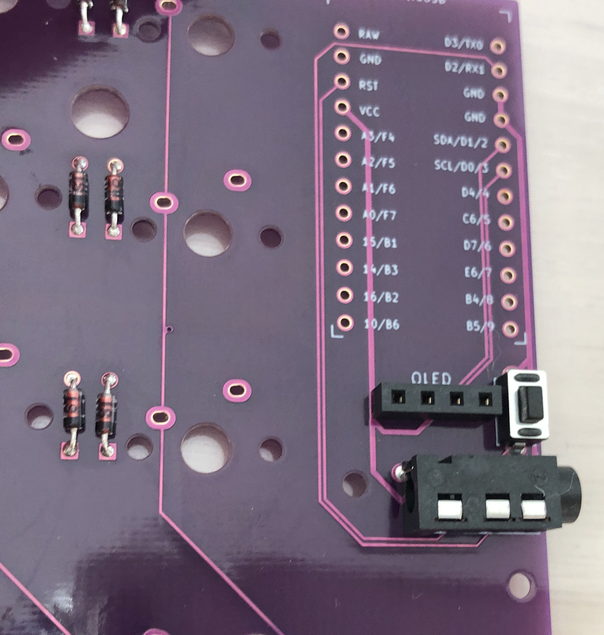
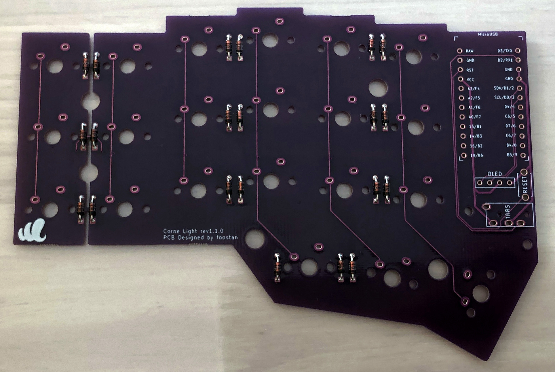 ### TRRSジャック、リセットスイッチ、ピンソケット
指定の位置に取り付けます。
※ 右手側も同じ位置に取り付けます(表裏の間違いに気を付けてください)。
### TRRSジャック、リセットスイッチ、ピンソケット
指定の位置に取り付けます。
※ 右手側も同じ位置に取り付けます(表裏の間違いに気を付けてください)。
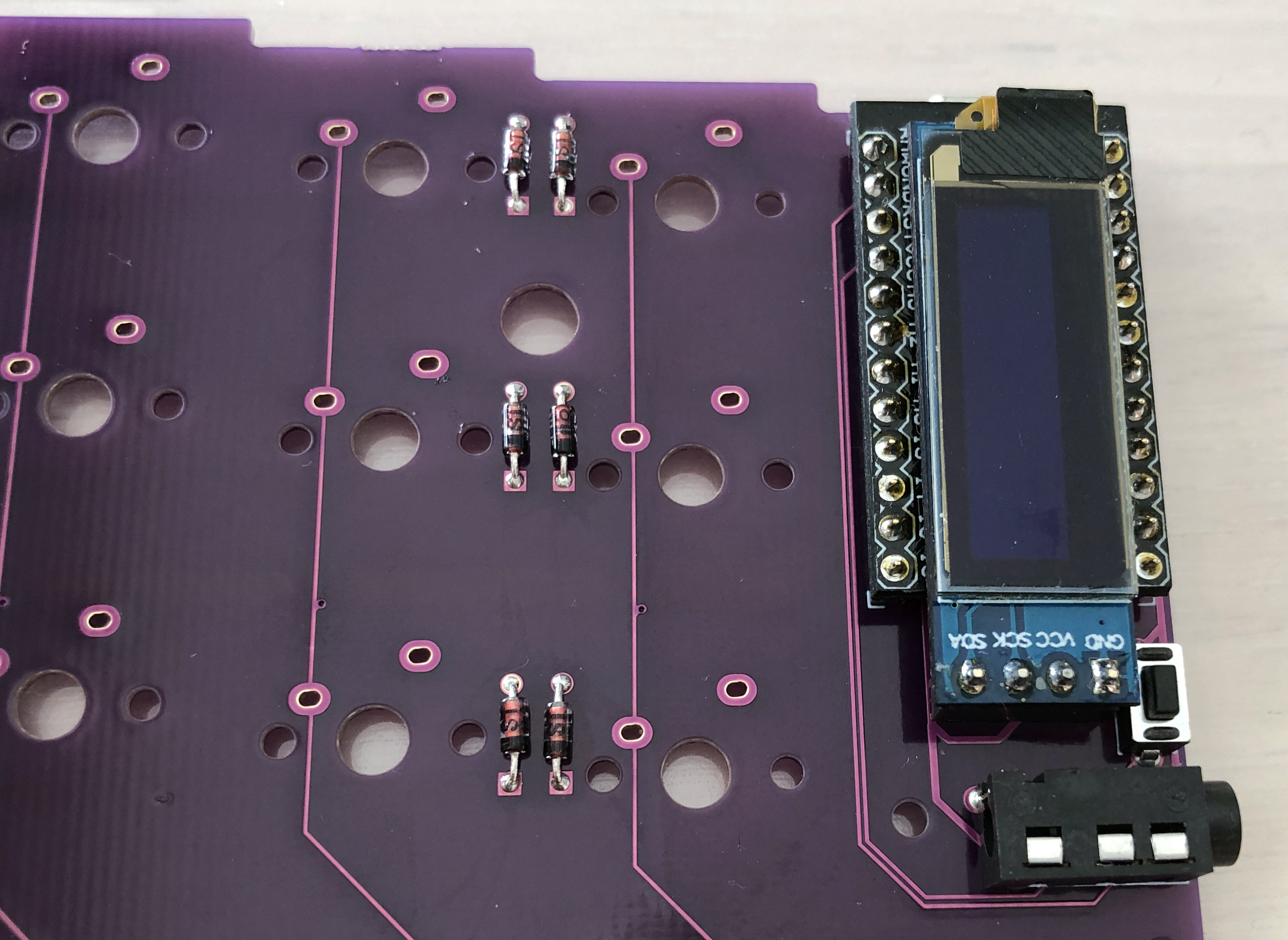
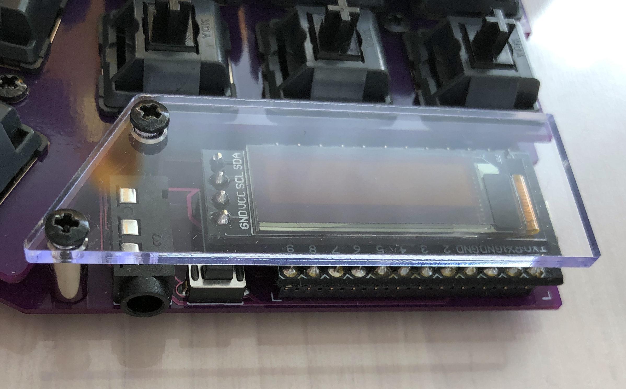
 ### ProMicro、OLEDモジュール
[Helix のビルドガイド](https://github.com/MakotoKurauchi/helix/blob/master/Doc/buildguide_jp.md#pro-micro)を参考にして ProMicro および OLED モジュールを取り付けます。
### ProMicro、OLEDモジュール
[Helix のビルドガイド](https://github.com/MakotoKurauchi/helix/blob/master/Doc/buildguide_jp.md#pro-micro)を参考にして ProMicro および OLED モジュールを取り付けます。
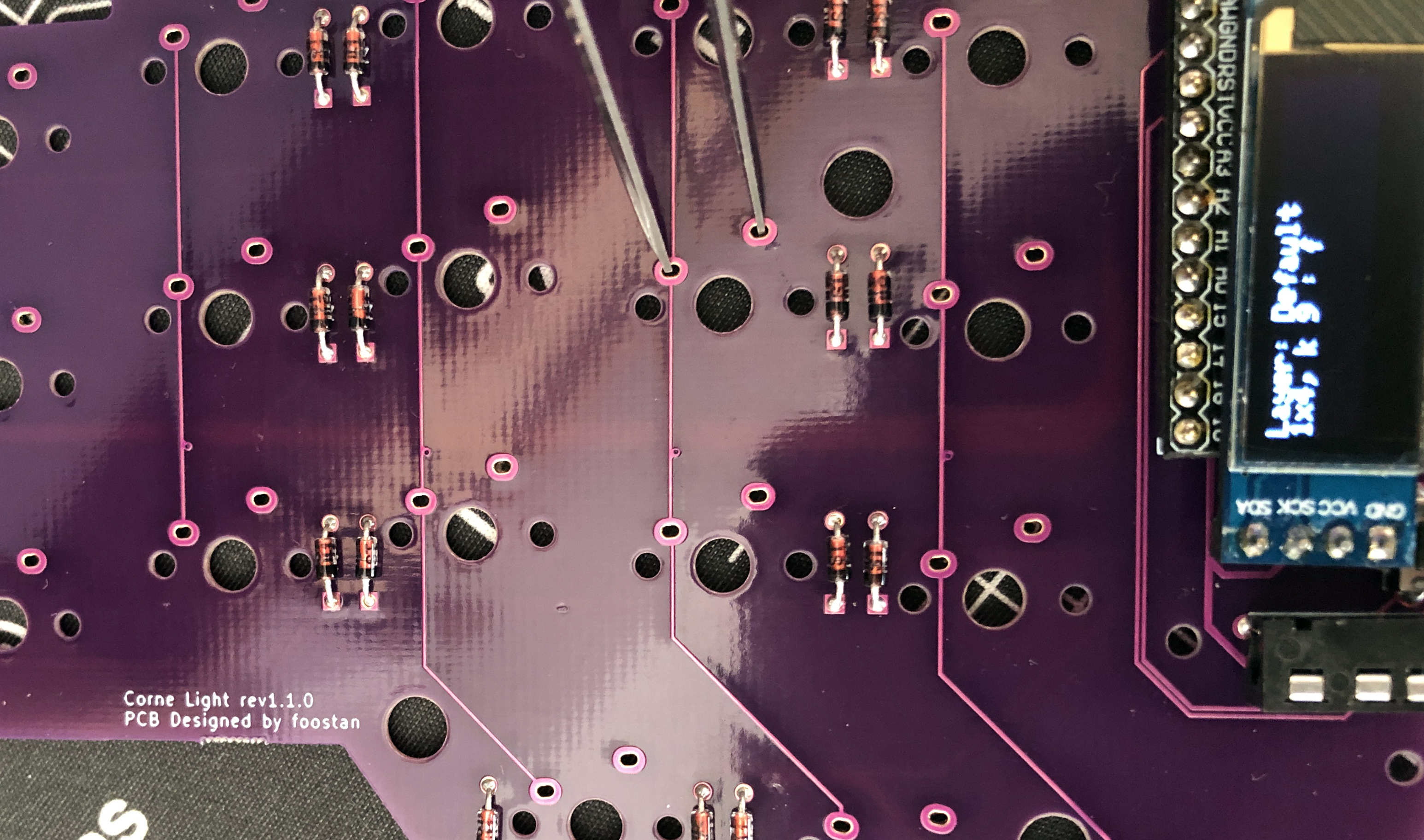
 ### ファームウェアの書き込み
下記を参照しファームウェアをProMicroに書き込みます。\
### ファームウェアの書き込み
下記を参照しファームウェアをProMicroに書き込みます。\
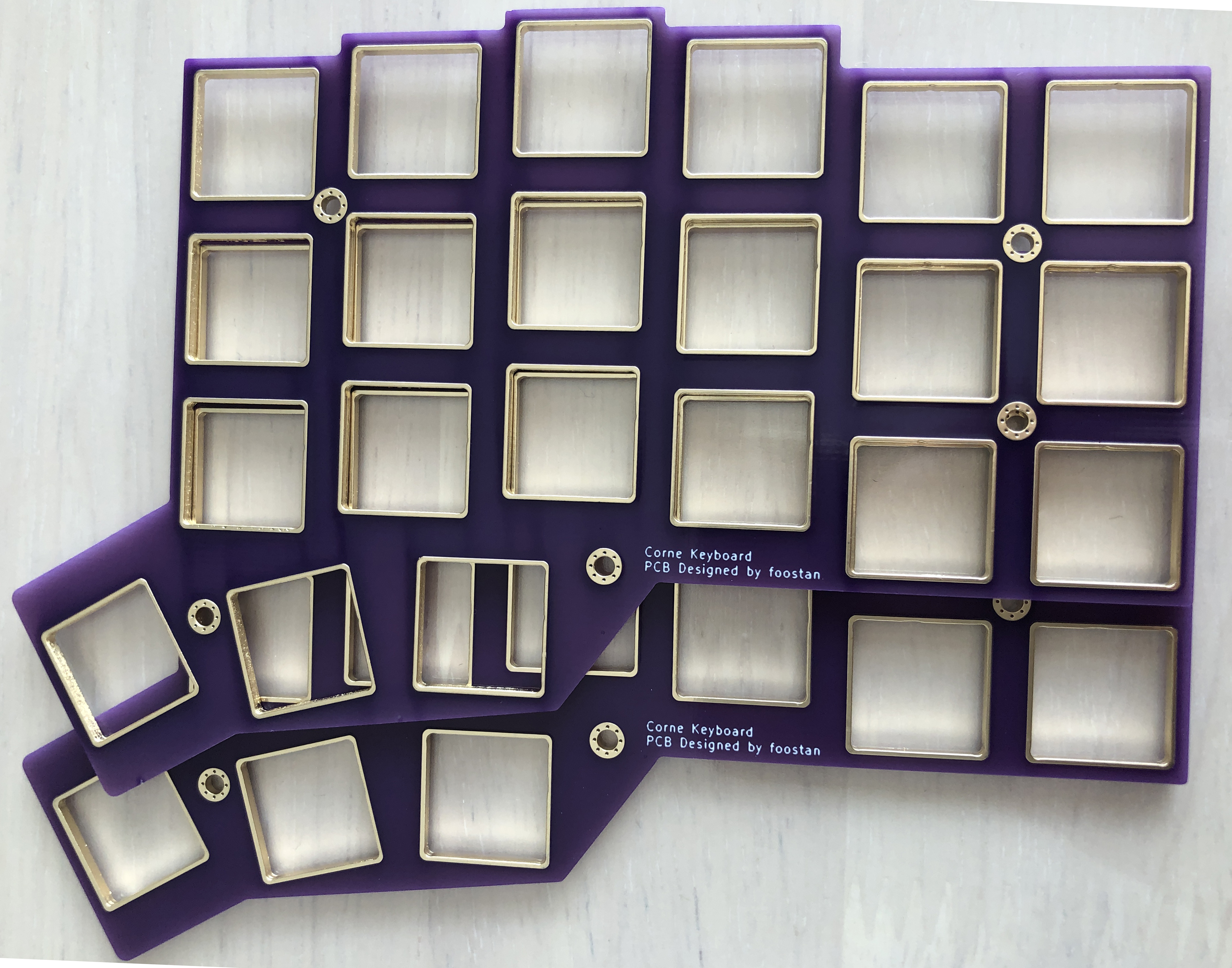
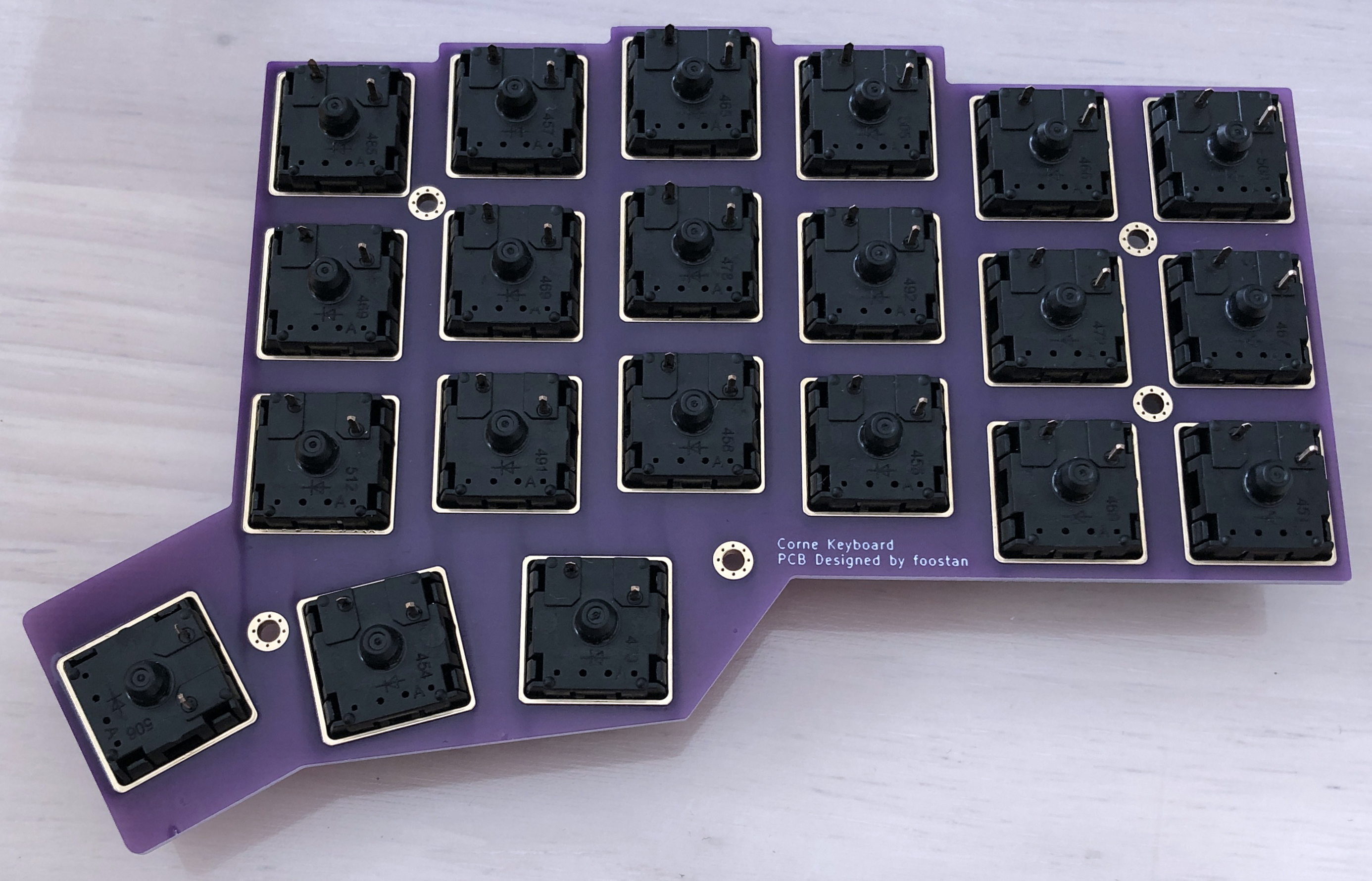
 ### トッププレート、キースイッチ
写真のようにトッププレートにキースイッチをはめます。
※ キースイッチの向きに気を付けてください。
### トッププレート、キースイッチ
写真のようにトッププレートにキースイッチをはめます。
※ キースイッチの向きに気を付けてください。
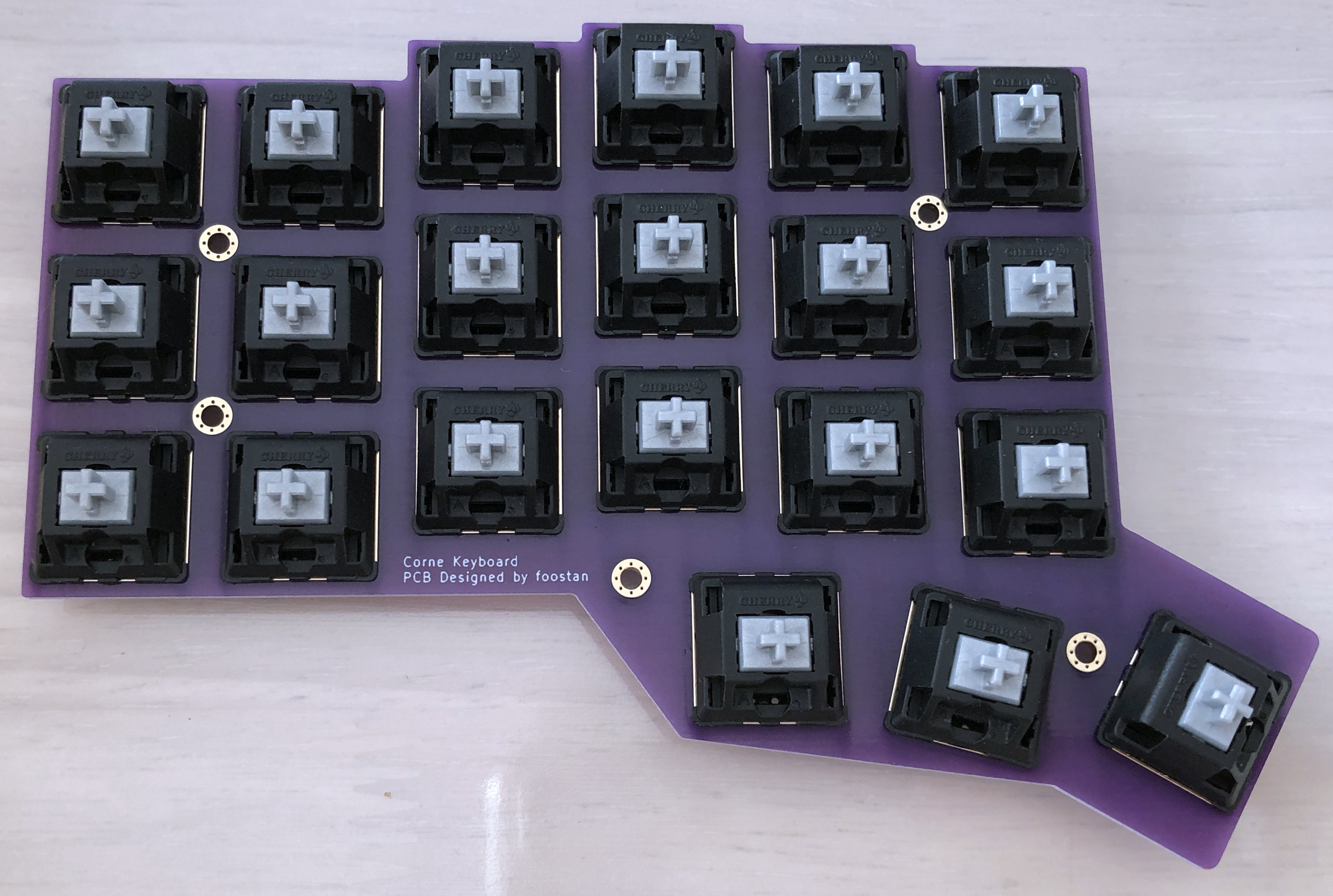 キースイッチは3ピンのものをおすすめします。
※ 5ピンを使用する場合でもプラスチックの足を切り離して3ピンにすることができます。
キースイッチは3ピンのものをおすすめします。
※ 5ピンを使用する場合でもプラスチックの足を切り離して3ピンにすることができます。
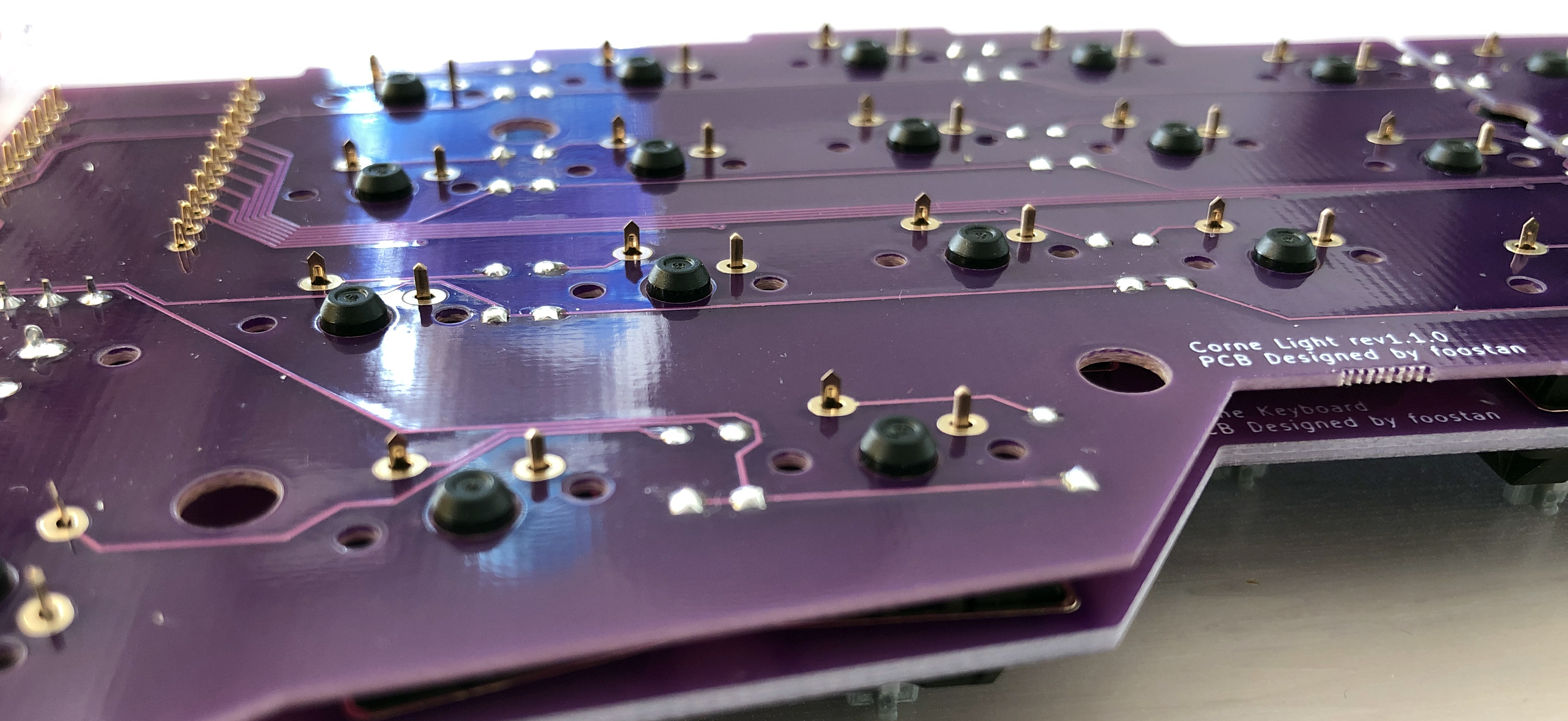
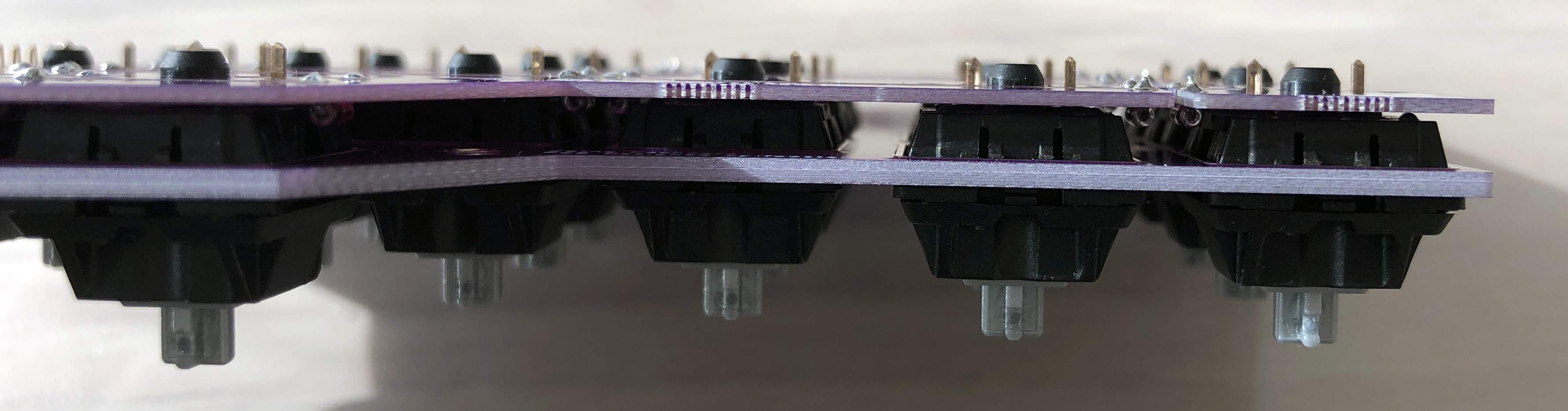
 スイッチとPCBの間に隙間ができないようにしてはんだ付けを行います。
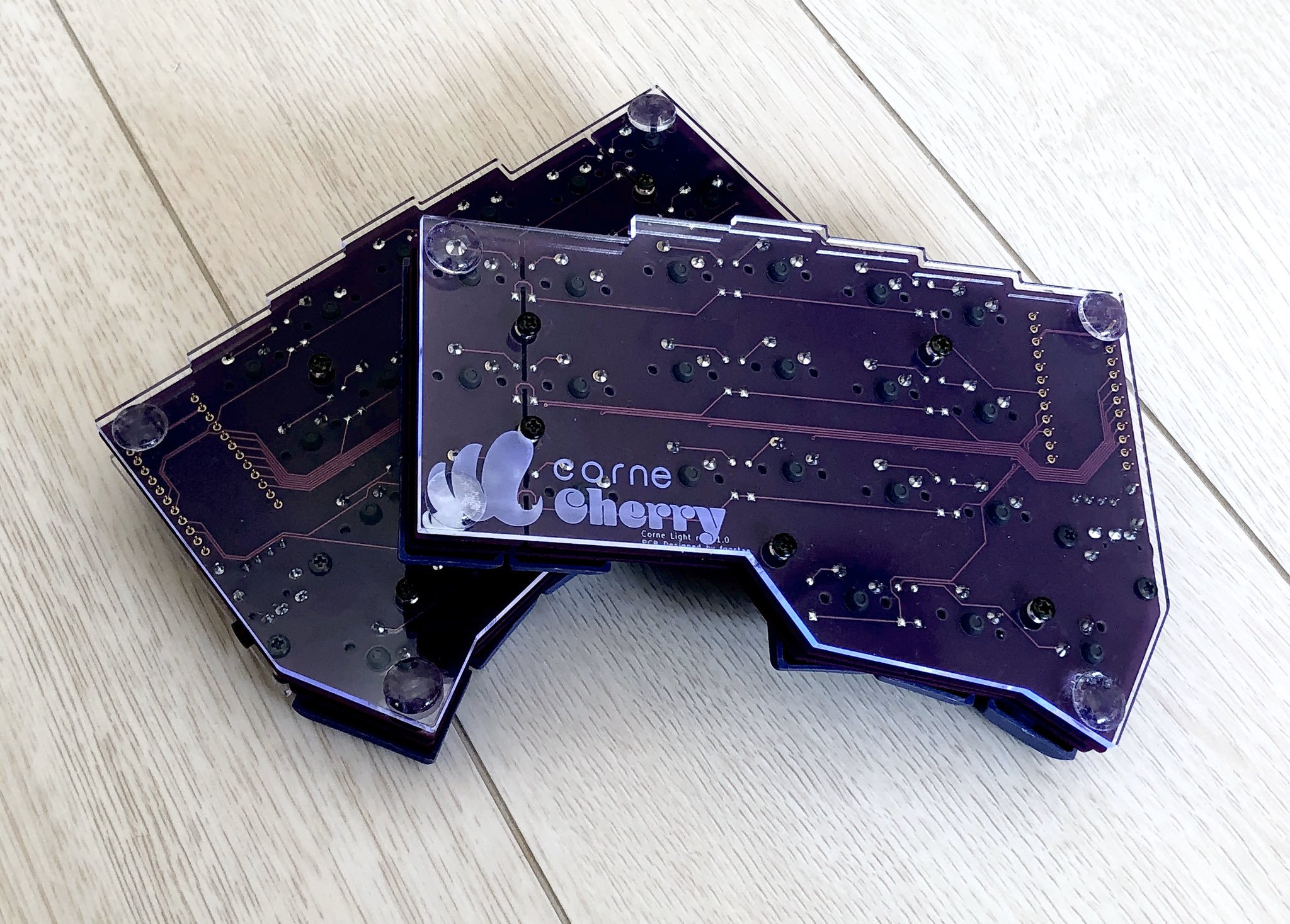
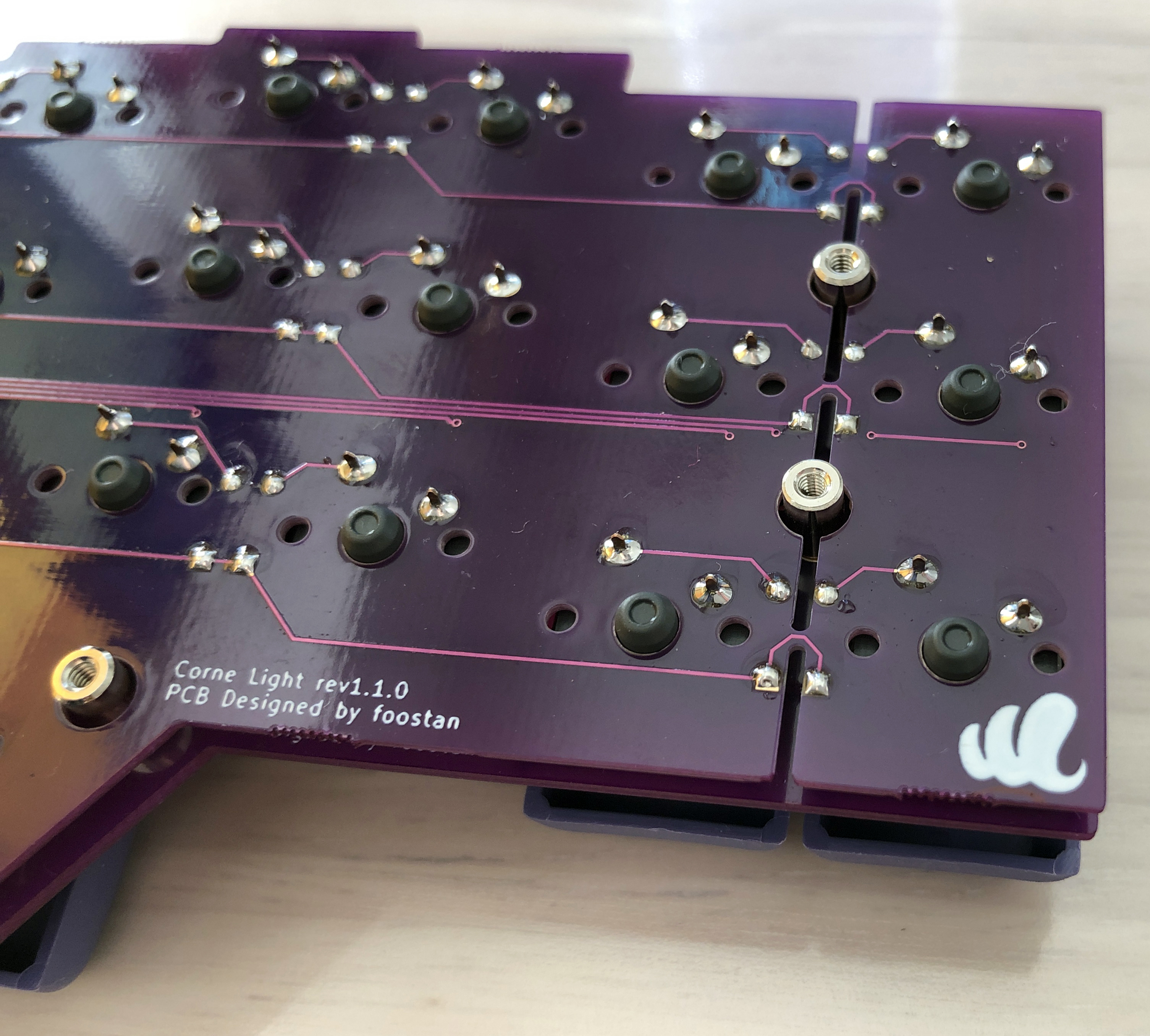
 ### ProMicro 保護プレート、ボトムプレート
M2 9mm スペーサーを用いて ProMicro 保護プレートを取り付けます。
### ProMicro 保護プレート、ボトムプレート
M2 9mm スペーサーを用いて ProMicro 保護プレートを取り付けます。
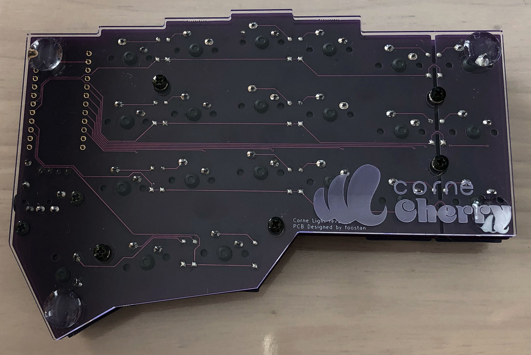
 M2 7.5mm スペーサーを用いてボトムプレートを取り付けます。
 4つ角にゴム足を取り付けます。
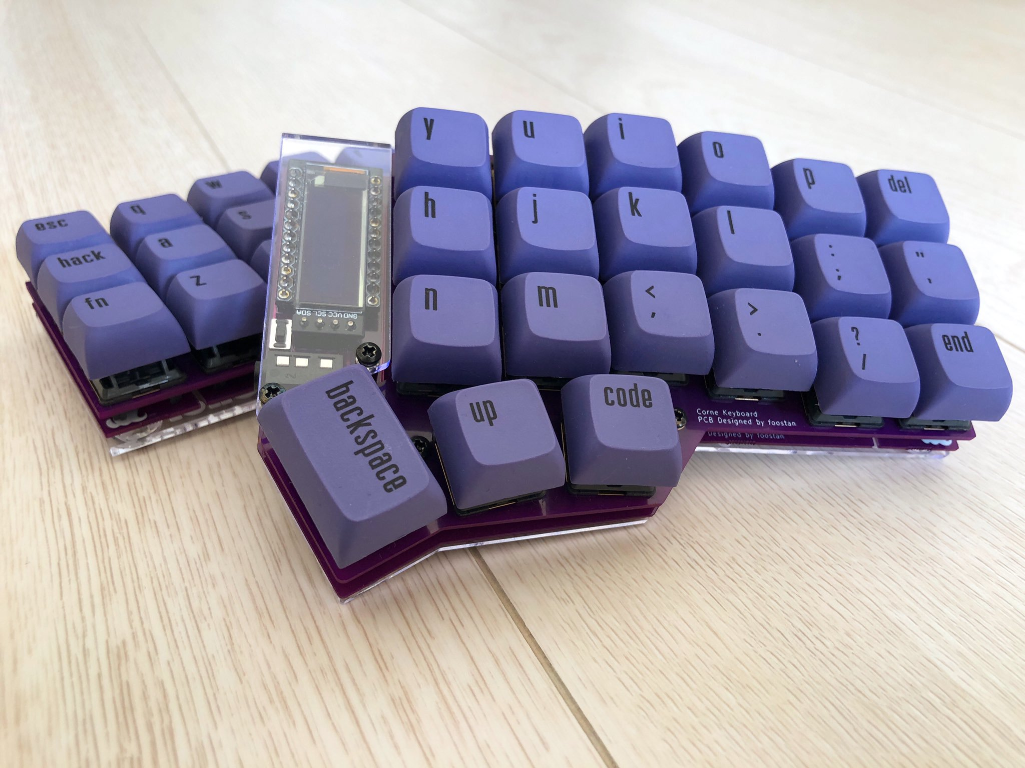
 ## 完成
キーキャップを取り付けて完成です。
## 完成
キーキャップを取り付けて完成です。