2018-12-11 08:09:42 +01:00
|
|
|
# Build Guide
|
|
|
|
|
|
|
|
|
|
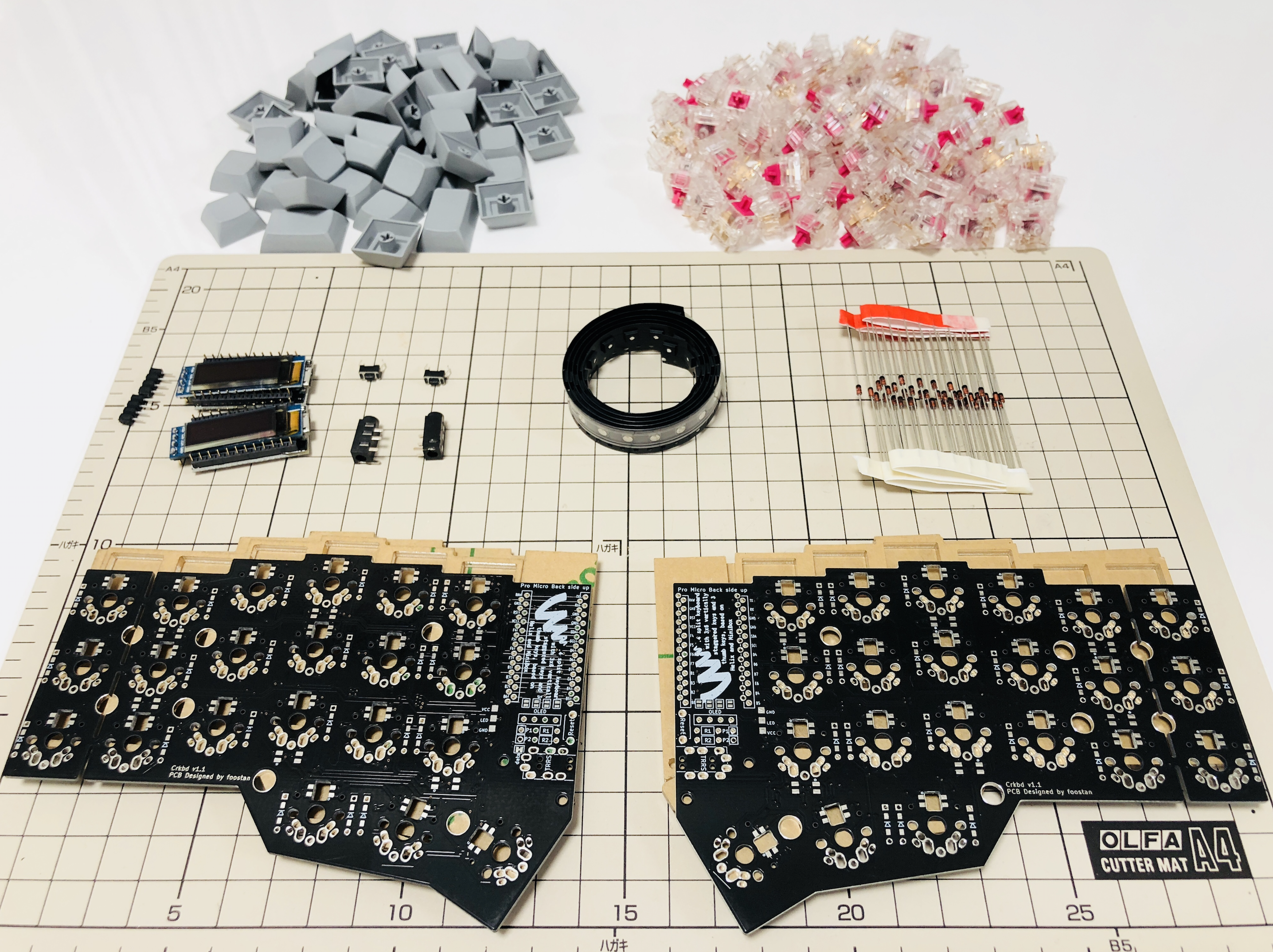
## Parts
|
2021-04-17 13:34:24 +02:00
|
|
|
|
2018-12-11 08:09:42 +01:00
|
|
|
### Required
|
2021-04-17 13:34:24 +02:00
|
|
|
|
2021-05-15 08:51:41 +02:00
|
|
|
| Name | Count | Remarks |
|
2018-12-11 08:09:42 +01:00
|
|
|
|:-|:-|:-|
|
|
|
|
|
| PCB | 2 | |
|
|
|
|
|
| Plate | 2 sets | |
|
|
|
|
|
| ProMicro | 2 | |
|
|
|
|
|
| TRRS Jack | 2 | |
|
|
|
|
|
| TRS(3 pole) cable | 1 | TRRS(4 pole) cable works too. |
|
|
|
|
|
| Tact switch | 2 | |
|
|
|
|
|
| Diode | 42 | You need SMD for low profile. |
|
|
|
|
|
| Key Switch | 42 | |
|
|
|
|
|
| Key Cap | 42 | 1u x 40, 1.5u x 2 |
|
2021-04-17 13:34:24 +02:00
|
|
|
| Spacer M2 7.5mm | 10 | use 3mm for low profile |
|
2020-12-01 00:41:17 +01:00
|
|
|
| Spacer M2 9mm or 11mm | 4 | |
|
|
|
|
|
| Screw M2 4mm | 28 | |
|
2018-12-11 08:09:42 +01:00
|
|
|
| Rubber foot | 10 | |
|
|
|
|
|
|
|
|
|
|
### Optional
|
2021-04-17 13:34:24 +02:00
|
|
|
|
2021-05-15 08:51:41 +02:00
|
|
|
| Name | Count | Remarks |
|
2018-12-11 08:09:42 +01:00
|
|
|
|:-|:-|:-|
|
|
|
|
|
| OLED Module | 1 or 2 | |
|
|
|
|
|
| 4x1 Pin Male Header | 2 | For OLED |
|
|
|
|
|
| 4x1 Pin Female Socket | 2 | For OLED |
|
|
|
|
|
| SK6812MINI | 54 | Front side x 42, back side x 12 |
|
|
|
|
|
| Addressable LED Strip | 2 | exclusive with SK6812MINI |
|
|
|
|
|
|
|
|
|
|
|
|
|
|
|
|
2021-05-15 08:52:32 +02:00
|
|
|
## Advance preparation
|
2021-04-17 13:34:24 +02:00
|
|
|
|
2021-04-17 15:09:15 +02:00
|
|
|
If you build the firmware yourself,
|
|
|
|
|
it will take some time to set up the environment,
|
|
|
|
|
so it's best to start at the beginning. \
|
|
|
|
|
For more information,
|
|
|
|
|
please see <https://github.com/foostan/crkbd/blob/master/doc/firmware_en.md>.
|
2020-11-03 07:18:38 +01:00
|
|
|
|
2018-12-11 08:09:42 +01:00
|
|
|
## Soldering
|
|
|
|
|
|
|
|
|
|
PCB is reversible; use one for the left hand side and the other for the right.
|
|
|
|
|
|
|
|
|
|
### Diodes
|
|
|
|
|
|
2021-04-17 15:07:04 +02:00
|
|
|
#### For non Low Profile keyswitches
|
2018-12-11 08:09:42 +01:00
|
|
|
|
2021-04-17 15:09:15 +02:00
|
|
|
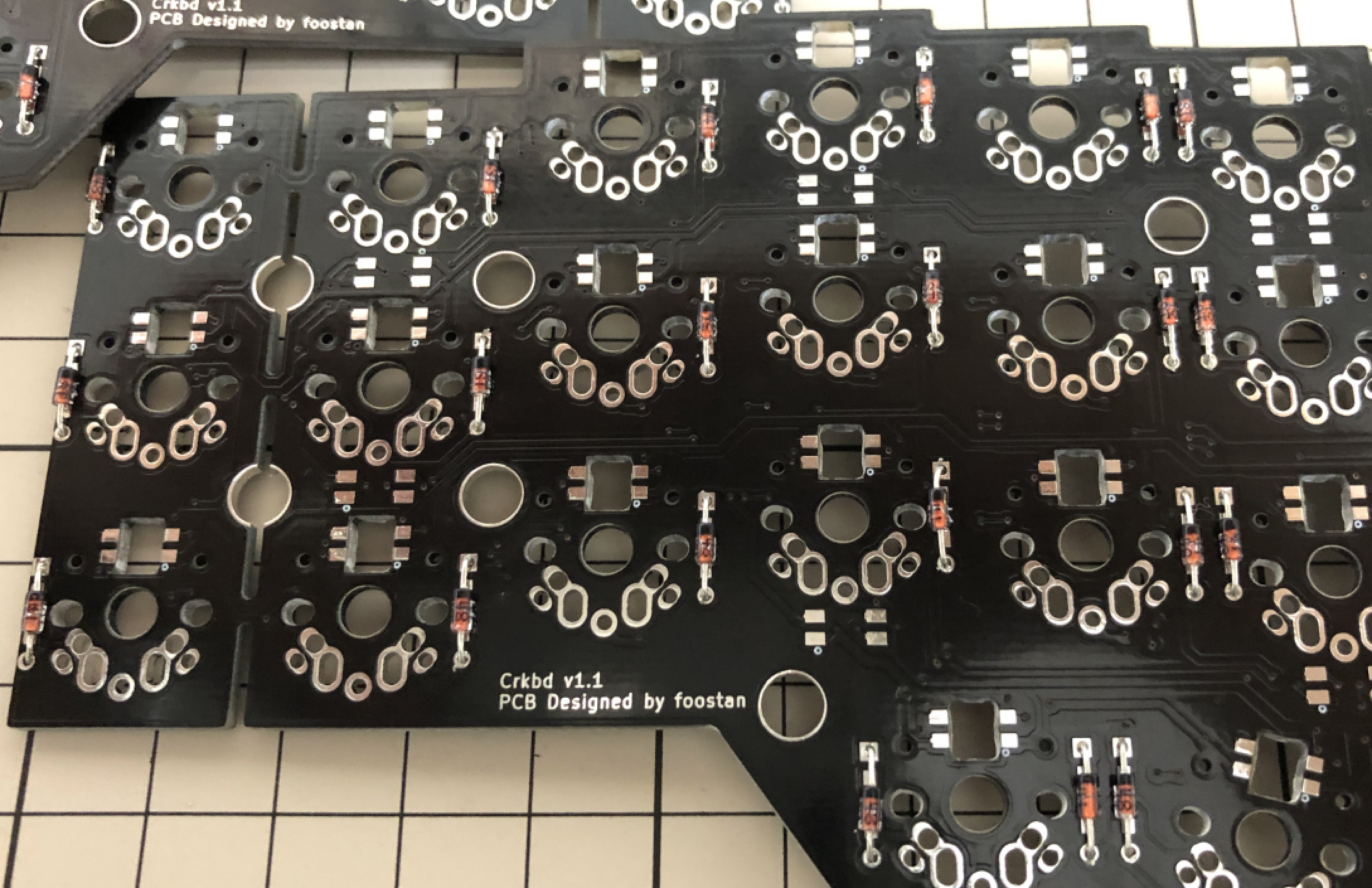
Solder diodes as indicated in the picture.
|
|
|
|
|
You can place it on either side,
|
|
|
|
|
but front side is recommended if you implement under-glow LED.
|
|
|
|
|
You can use SMD diodes too.
|
2018-12-11 08:09:42 +01:00
|
|
|
|
2021-04-17 15:09:15 +02:00
|
|
|
|
2018-12-11 08:09:42 +01:00
|
|
|
|
2021-04-17 15:09:15 +02:00
|
|
|
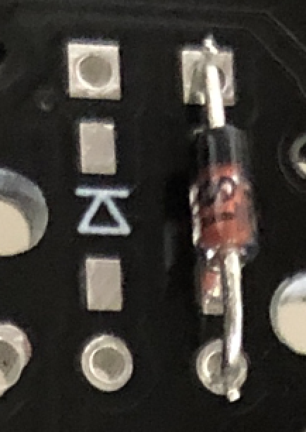
Diode has polarity;
|
|
|
|
|
make sure to match the polarity with PCB silkscreen.
|
2018-12-11 08:09:42 +01:00
|
|
|
|
|
|
|
|
<- Before | After ->
|
|
|
|
|
|
|
|
|
|
|
|
|
|
|
|
2021-04-17 15:07:04 +02:00
|
|
|
#### For Low Profile Keyswitches
|
2018-12-11 08:09:42 +01:00
|
|
|
|
2021-04-17 15:09:15 +02:00
|
|
|
If you use low profile keyswitches,
|
|
|
|
|
you have to implement SMD diodes __on the back side__.
|
2018-12-11 08:09:42 +01:00
|
|
|
Otherwise, diodes will interfere with top plate.
|
|
|
|
|
|
2021-04-17 15:09:15 +02:00
|
|
|
As with normal diodes,
|
|
|
|
|
[SMD diodes have polarity](https://learn.sparkfun.com/tutorials/polarity/diode-and-led-polarity).
|
|
|
|
|
The lines on the SMD diode should be on the same side as the line on the PCB silkscreen.
|
2018-12-11 08:09:42 +01:00
|
|
|
|
|
|
|
|
### LEDs (Optional)
|
|
|
|
|
|
2021-04-17 15:09:15 +02:00
|
|
|
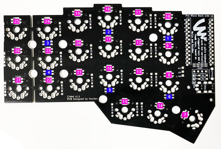
Implement LEDs under keyswitches (No. 7 through 27) upward facing,
|
|
|
|
|
and others (No. 1 through 6) on the back side(under-glow),
|
|
|
|
|
as indicated in the picture.
|
2018-12-11 08:09:42 +01:00
|
|
|
|
|
|
|
|
|
|
|
|
|
|
|
|
|
|
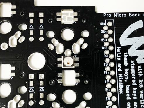
For No.7 to 27 LEDs, __Install LEDs from the back side__ as shown below.
|
2021-04-17 15:09:15 +02:00
|
|
|
Note the '**o**' silkscreen marking
|
|
|
|
|
and use them as a guide to implement LEDs in the direction.
|
|
|
|
|
On some versions of the PCB (e.g. Corne-cherry v2),
|
|
|
|
|
the '**o**' silkscreen marking has been replaced by a white square
|
|
|
|
|
around one of the pads,
|
|
|
|
|
but the principle is still the same.
|
2018-12-11 08:09:42 +01:00
|
|
|
|
|
|
|
|
|
|
|
|
|
|
2021-04-17 15:09:15 +02:00
|
|
|
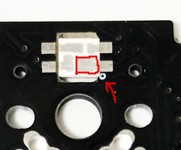
The LED has one pad that is shaped like a square.
|
|
|
|
|
That square should connect to the pad that has the '**o**' silkscreen marking:
|
2018-12-11 08:09:42 +01:00
|
|
|
|
2019-10-10 16:30:04 +02:00
|
|
|
|
|
|
|
|
|
2021-04-17 15:09:15 +02:00
|
|
|
There are many different techniques on how to solder the LEDs,
|
|
|
|
|
but [this video](https://twitter.com/foostan/status/1005656803818889216)
|
|
|
|
|
might give you an idea on how to do it.
|
2018-12-11 08:09:42 +01:00
|
|
|
|
2021-04-17 15:09:15 +02:00
|
|
|
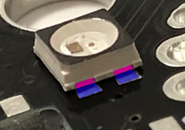
For No. 1 to 6 LEDs, solder the pattern on the side of the device
|
|
|
|
|
(highlighted in pink on the picture) and the PCB pattern (blue on the picture).
|
|
|
|
|
Apply flux and take small amount of solder with a soldering iron
|
|
|
|
|
and press it on the edge of the patterns.
|
2018-12-11 08:09:42 +01:00
|
|
|
|
|
|
|
|
|
|
|
|
|
|
2021-04-17 15:09:15 +02:00
|
|
|
LEDs are connected in the order of the number on the picture above.
|
|
|
|
|
If it turns on only halfway,
|
|
|
|
|
it is likely that first LED that doesn't turn on
|
|
|
|
|
or the last LED that turns on is not implemented correctly.
|
2018-12-11 08:09:42 +01:00
|
|
|
|
2021-04-17 15:09:15 +02:00
|
|
|
__Note__ that the default Crkbd firmware has __LEDs turned off__,
|
|
|
|
|
so you'll have to turn them on before you can test
|
|
|
|
|
(see the firmware section for instructions how).
|
2018-12-11 08:09:42 +01:00
|
|
|
|
|
|
|
|
### Jumpers for OLED modules (optional)
|
2021-04-17 13:34:24 +02:00
|
|
|
|
2018-12-11 08:09:42 +01:00
|
|
|
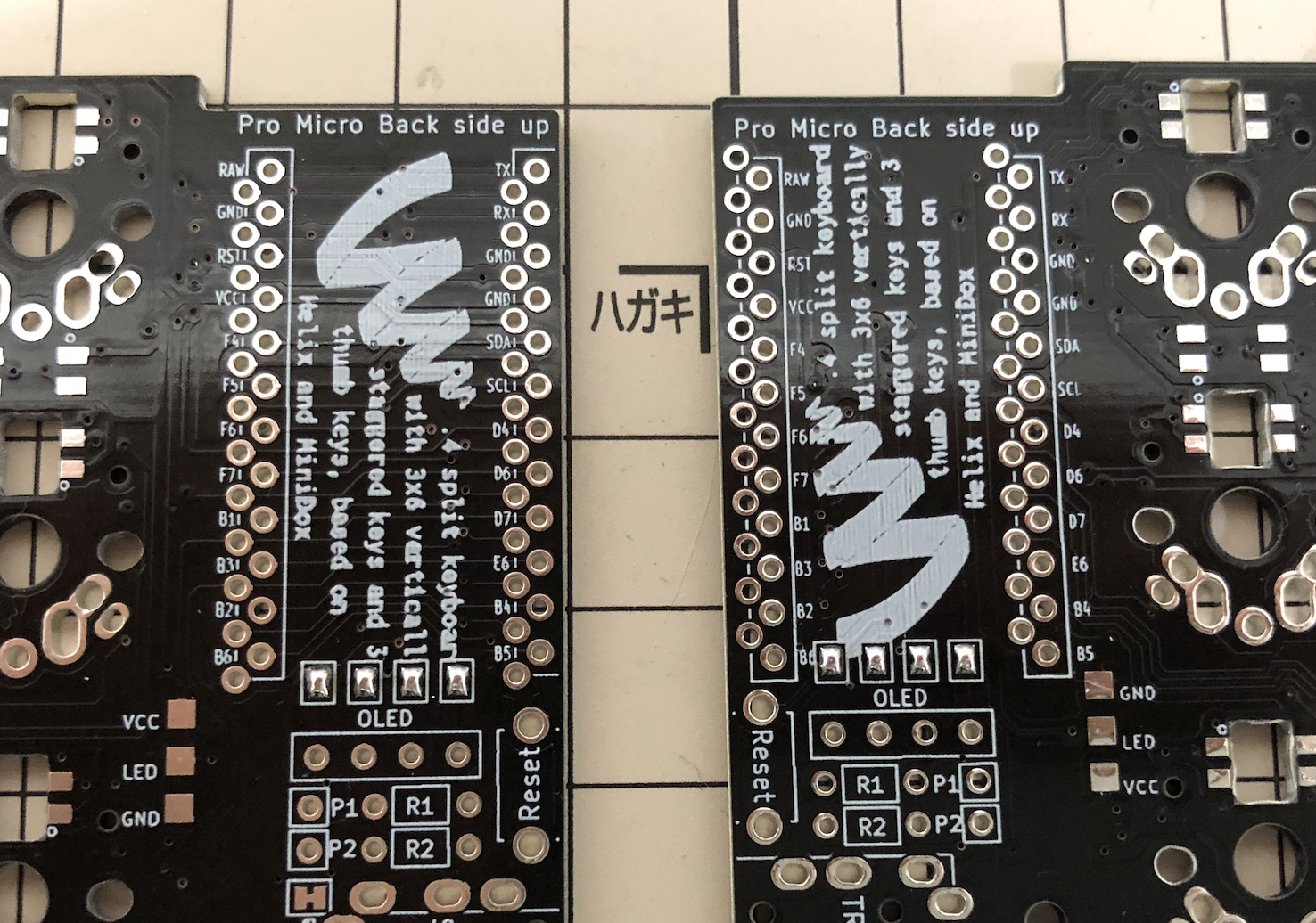
To use OLED modules, short circuit the jumper patterns.
|
|
|
|
|
__Only short circuit the front side__
|
|
|
|
|
|
|
|
|
|
|
|
|
|
|
|
2021-04-17 13:34:24 +02:00
|
|
|
### TRRS socket, reset switch, OLED header sockets
|
2018-12-11 08:09:42 +01:00
|
|
|
|
|
|
|
|
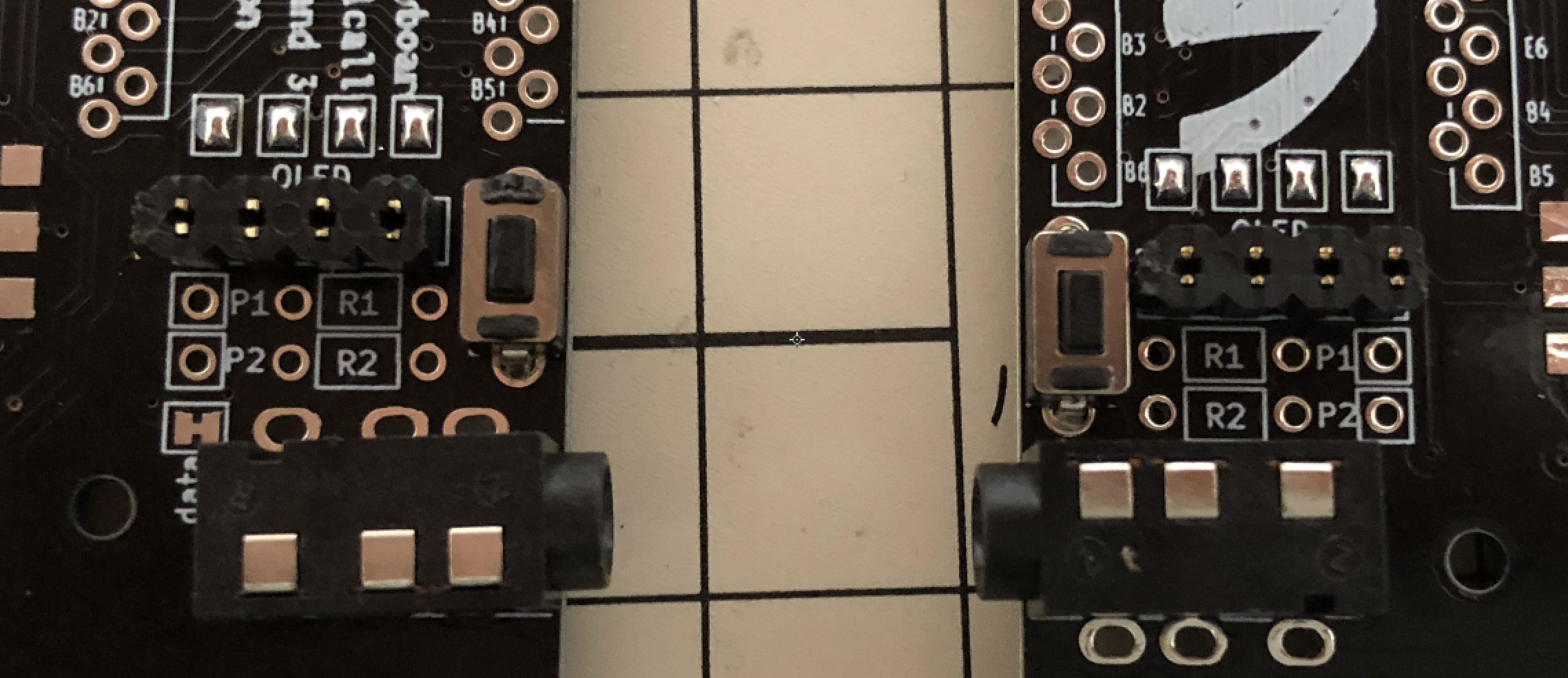
Install TRRS sockets and reset switches as in the picture.
|
|
|
|
|
For OLEDs, also implement pin sockets.
|
|
|
|
|
|
|
|
|
|
|
|
|
|
|
|
|
|
|
|
### ProMicro
|
|
|
|
|
|
2021-04-17 15:09:15 +02:00
|
|
|
Before you start,
|
|
|
|
|
flash the Crkbd firmware to the ProMicros to make sure they are alright.
|
2018-12-11 08:09:42 +01:00
|
|
|
|
2021-04-17 15:09:15 +02:00
|
|
|
The ProMicro is then installed
|
|
|
|
|
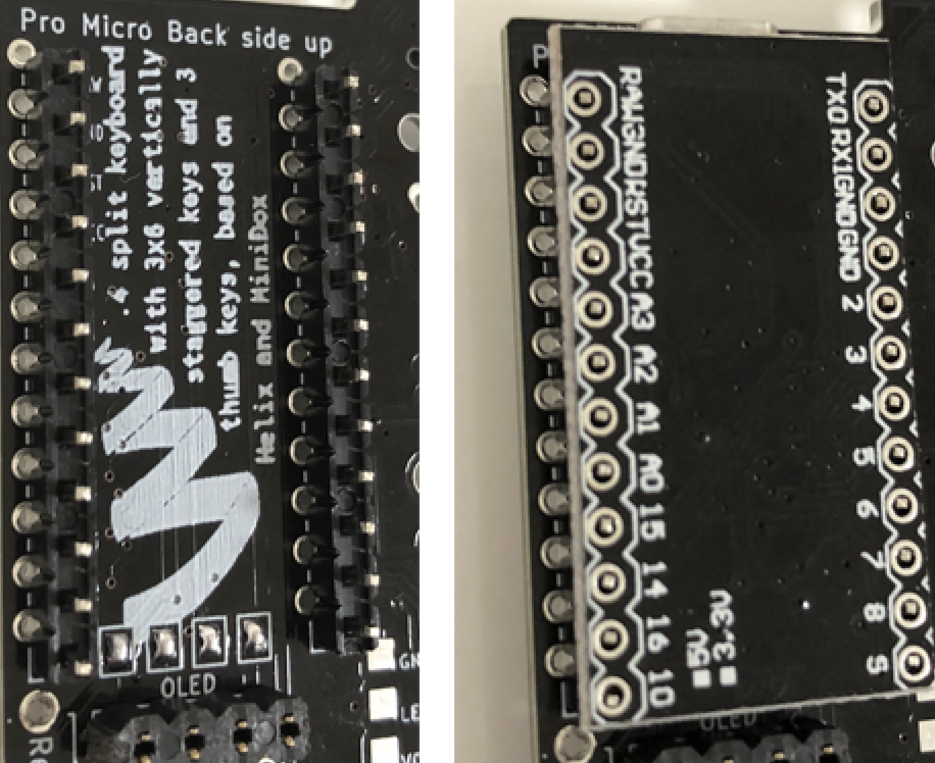
__in the set of holes that has a white frame on the frontside of the PCB__.
|
|
|
|
|
Make sure you solder it in the right set of holes,
|
|
|
|
|
as desoldering the ProMicro is hard.
|
|
|
|
|
Implement pin headers in the white frame,
|
|
|
|
|
then install ProMicro with its __backside up__.
|
2018-12-11 08:09:42 +01:00
|
|
|
|
|
|
|
|
|
|
|
|
|
|
2021-04-17 15:09:15 +02:00
|
|
|
The picture is the right hand side, but it's the same for the left hand side -
|
|
|
|
|
pins into the through holes in the white frame as seen from the frontside,
|
|
|
|
|
placing the ProMicro with its backside up.
|
2019-10-10 16:32:39 +02:00
|
|
|
|
2018-12-11 08:09:42 +01:00
|
|
|
### OLED Module
|
2021-04-17 13:34:24 +02:00
|
|
|
|
2021-04-17 15:09:15 +02:00
|
|
|
Implement pin header onto the OLED modules,
|
|
|
|
|
then insert them into the pin sockets.
|
2018-12-11 08:09:42 +01:00
|
|
|
|
|
|
|
|

|
|
|
|
|
|
|
|
|
|
Adjust the height of the spacer accordingly to the height of pin header.
|
2020-12-01 00:41:17 +01:00
|
|
|
Most common pin header/socket and 11mm spacers are used in the picture.
|
2018-12-11 08:09:42 +01:00
|
|
|
|
|
|
|
|
### Use socket to Mount ProMicro
|
|
|
|
|
|
2021-04-17 15:09:15 +02:00
|
|
|
With using sockets for mounting ProMicro,
|
|
|
|
|
you can replace it easily when it breaks.
|
|
|
|
|
Two methods are introduced here.
|
2018-12-11 08:09:42 +01:00
|
|
|
|
|
|
|
|
#### Using Spring Loaded Header
|
|
|
|
|
|
2021-05-15 11:20:11 +02:00
|
|
|
Refer to the [Helix build guide](
|
|
|
|
|
https://github.com/MakotoKurauchi/helix/blob/master/Doc/buildguide_en.md#pro-micro)
|
2018-12-11 08:09:42 +01:00
|
|
|
|
|
|
|
|
ProMicro kit with spring loaded headers is available at Yusha-Kobo
|
|
|
|
|
|
2021-04-17 13:34:24 +02:00
|
|
|
<https://yushakobo.jp/shop/promicro-spring-pinheader/>
|
2018-12-11 08:09:42 +01:00
|
|
|
|
2021-04-17 15:09:15 +02:00
|
|
|
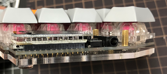
Using OLEDs available at Yusha-Kobo which come with low profile header,
|
2022-01-30 12:21:45 +01:00
|
|
|
together with and 9mm spacers, you can build them thin and gap-less.
|
2018-12-11 08:09:42 +01:00
|
|
|
|
|
|
|
|
|
|
|
|
|
|
|
|
|
|
#### Using Pin Sockets
|
2021-04-17 13:34:24 +02:00
|
|
|
|
2018-12-11 08:09:42 +01:00
|
|
|
Low profile pin sockets are available from Akizuki Denshi etc. Requires some work.
|
|
|
|
|
|
2021-04-17 13:34:24 +02:00
|
|
|
<http://akizukidenshi.com/catalog/g/gC-03138/>
|
2018-12-11 08:09:42 +01:00
|
|
|
|
|
|
|
|
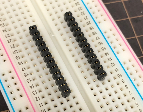
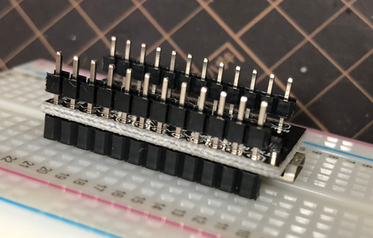
Install a couple of 12x1 pin sockets on a breadboard.
|
|
|
|
|
|
|
|
|
|
|
|
|
|
|
|
|
|
|
|
Using male 12x1 pin headers, fixate ProMicro onto the pin sockets.
|
|
|
|
|
|
|
|
|
|
|
|
|
|
|
|
2021-04-17 15:09:15 +02:00
|
|
|
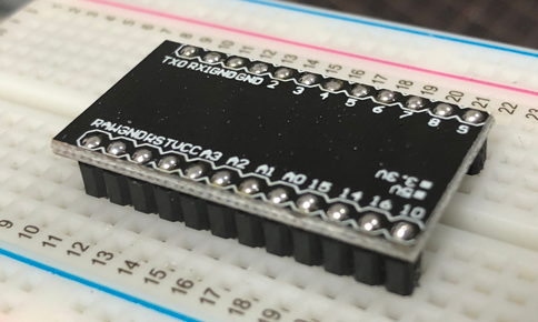
Remove plastic pin holders, solder the pins to ProMicro,
|
|
|
|
|
and then cut extra pins.
|
2018-12-11 08:09:42 +01:00
|
|
|
|
|
|
|
|
|
|
|
|
|
|
|
|
|
|
#### Comparison
|
|
|
|
|
|
|
|
|
|
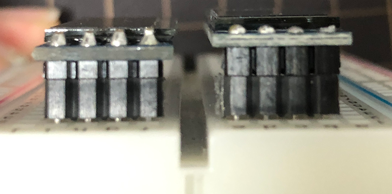
Spring loaded headers can make the height lower.
|
|
|
|
|
|
|
|
|
|

|
|
|
|
|
|
2021-04-17 15:09:15 +02:00
|
|
|
Comparing pin-headers in the picture.
|
|
|
|
|
Headers come with OLED available at Yusha-Kobo are lower.
|
2018-12-11 08:09:42 +01:00
|
|
|
|
|
|
|
|
|
|
|
|
|
|
|
|
|
|
### Testing
|
|
|
|
|
|
2021-04-17 15:09:15 +02:00
|
|
|
It is recommended to test the ProMicro and OLED modules
|
|
|
|
|
before installing keyswitches,
|
|
|
|
|
because rework would be difficult after that.
|
2018-12-11 08:09:42 +01:00
|
|
|
|
2021-04-17 15:09:15 +02:00
|
|
|
First, build QMK Firmware for built for Crkbd
|
|
|
|
|
and install on ProMicro (if you haven't already done so).
|
2019-10-10 16:34:59 +02:00
|
|
|
|
2021-04-17 15:09:15 +02:00
|
|
|
|
2019-10-10 16:34:59 +02:00
|
|
|
|
2021-04-17 15:09:15 +02:00
|
|
|
Using the default keymap,
|
|
|
|
|
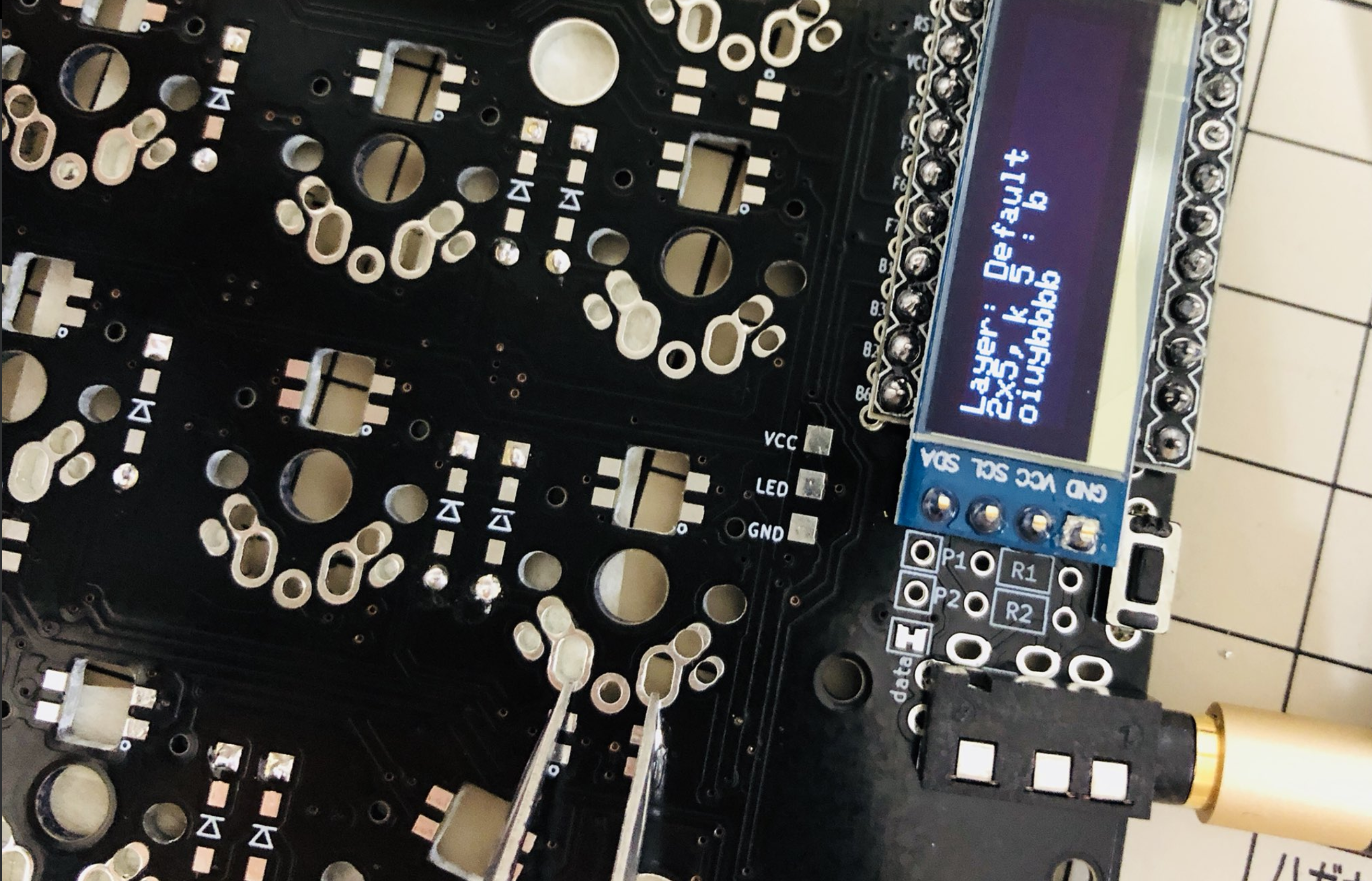
OLED will show information on the keyswitches being pressed.
|
|
|
|
|
Check the connections by short-circuiting keyswitch soldering pads
|
|
|
|
|
with tweezers or a bit of soldering wire.
|
|
|
|
|
Check all of them.
|
|
|
|
|
|
|
|
|
|
If you have OLED displays,
|
|
|
|
|
you can verify that all keys are responding
|
|
|
|
|
by looking at the log information showed there.
|
|
|
|
|
It will say which row and column was pressed,
|
|
|
|
|
e.g. `1x5` or `0x2`. Using the tweezers or wire,
|
|
|
|
|
connect each buttons soldering pads and make sure the display changes.
|
|
|
|
|
If something isn't working,
|
|
|
|
|
take note of the which row x column it is that isn't working,
|
|
|
|
|
as it can help when troubleshooting.
|
|
|
|
|
|
|
|
|
|
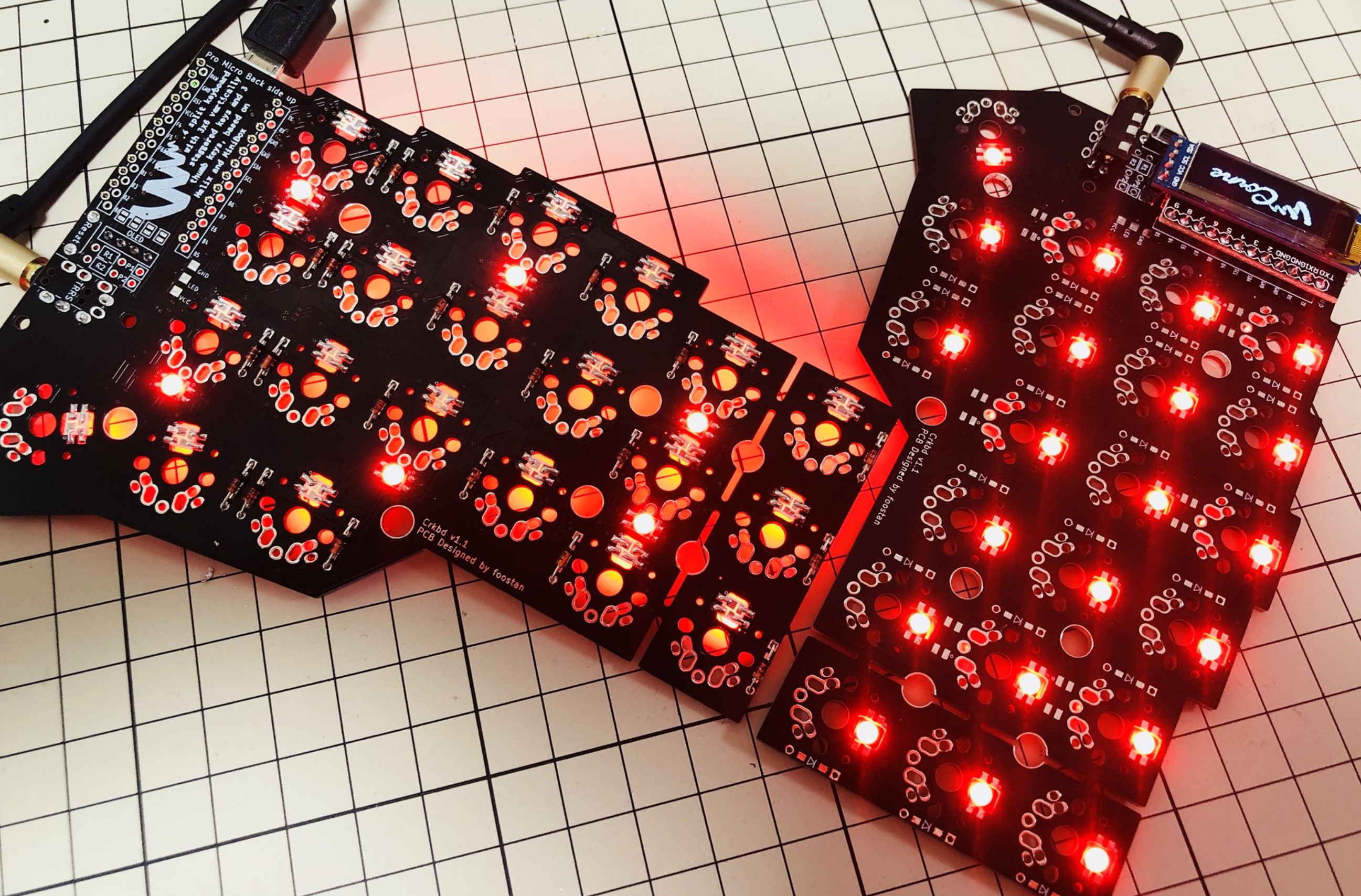
If you have mounted LEDs,
|
|
|
|
|
also make sure all of them are turned on.
|
|
|
|
|
As note before, the default firmware has LEDs __turned off__,
|
|
|
|
|
so you have to turn them on in the firmware before you test.
|
2018-12-11 08:09:42 +01:00
|
|
|
|
|
|
|
|
|
|
|
|
|
|
|
|
|
|
### Keyswitches and Top Plate
|
2021-04-17 13:34:24 +02:00
|
|
|
|
2018-12-11 08:09:42 +01:00
|
|
|
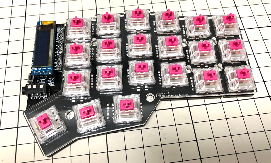
Sandwich top-plate with PCB and key-switches.
|
|
|
|
|
|
|
|
|
|
|
|
|
|
|
|
|
|
|
|
### Bottom Plate
|
2021-04-17 13:34:24 +02:00
|
|
|
|
2018-12-11 08:09:42 +01:00
|
|
|
Use 3mm spacers for low-profile,
|
2020-12-01 00:41:17 +01:00
|
|
|
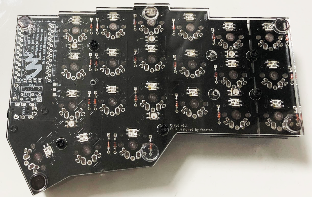
Attach bottom plate to the PCB using 7.5mm (3mm for low-profile) spacers.
|
2018-12-11 08:09:42 +01:00
|
|
|
Then attach six rubber feet.
|
|
|
|
|
|
|
|
|
|
|
|
|
|
|
|
|
|
|
|
### Keycaps
|
2021-04-17 13:34:24 +02:00
|
|
|
|
2018-12-11 08:09:42 +01:00
|
|
|
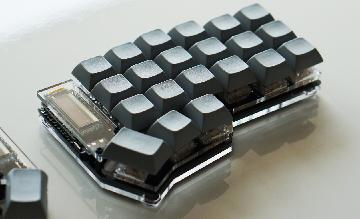
Lastly install keycaps.
|
|
|
|
|
|
|
|
|
|
|
|
|
|
|
|
|
|
|
|
## Firmware
|
2021-04-17 13:34:24 +02:00
|
|
|
|
2020-11-03 07:18:38 +01:00
|
|
|
See below to flash the firmware to the ProMicro. \
|
2021-04-17 13:34:24 +02:00
|
|
|
<https://github.com/foostan/crkbd/blob/master/doc/firmware_en.md>
|
2018-12-11 08:09:42 +01:00
|
|
|
|
2019-10-10 16:38:44 +02:00
|
|
|
### Turning LEDS on
|
2021-04-17 13:34:24 +02:00
|
|
|
|
2021-04-17 15:09:15 +02:00
|
|
|
To turn the LEDs on, you have to edit the `rules.mk` file.
|
|
|
|
|
If you use the default layout,
|
|
|
|
|
it can be found here `keyboards/crkbd/keymaps/default/rules.mk`.
|
|
|
|
|
Add the following line to the top of the file:
|
2021-04-17 13:34:24 +02:00
|
|
|
|
2019-10-10 16:38:44 +02:00
|
|
|
```
|
2019-12-29 03:59:59 +01:00
|
|
|
RGBLIGHT_ENABLE = yes
|
2019-10-10 16:38:44 +02:00
|
|
|
```
|
|
|
|
|
|
2021-04-17 15:09:15 +02:00
|
|
|
Compile and flash to both sides and all LEDs should turn on
|
|
|
|
|
and __glow red__ if you have soldered everything correctly.
|
|
|
|
|
If you run the default firmware and the LEDs turn a differrent color,
|
|
|
|
|
the data to the LEDs is probably corrupted somewhere along the way.
|
|
|
|
|
Check the LED before the first one
|
|
|
|
|
turning a different color using the troubleshooting guide below.
|
2018-12-11 08:09:42 +01:00
|
|
|
|
2020-07-06 08:58:38 +02:00
|
|
|
## Troubleshooting
|
2021-04-17 13:34:24 +02:00
|
|
|
|
2020-07-06 08:58:38 +02:00
|
|
|
Here are some tips and tricks on how to troubleshot a board that is not working.
|
|
|
|
|
|
|
|
|
|
### No LEDs turn on
|
2021-04-17 13:34:24 +02:00
|
|
|
|
2021-04-17 15:09:15 +02:00
|
|
|
There are a number of things that might be wrong.
|
|
|
|
|
First of all, make sure you have __turned on LED lighting in the firmware__.
|
|
|
|
|
If that is the case, then chances are there might be a problem with the first LED.
|
|
|
|
|
Try the suggestions in the next section.
|
2020-07-06 08:58:38 +02:00
|
|
|
|
|
|
|
|
### Some LEDs not turning on
|
2021-04-17 13:34:24 +02:00
|
|
|
|
2021-04-17 15:09:15 +02:00
|
|
|
If some LEDs aren't turning on,
|
|
|
|
|
check the first LED not turning on __or__ the one before it.
|
2020-07-06 08:58:38 +02:00
|
|
|
|
|
|
|
|

|
|
|
|
|
|
|
|
|
|
Here are some things to try out:
|
2021-04-17 13:34:24 +02:00
|
|
|
|
2021-04-17 15:09:15 +02:00
|
|
|
- Make sure the LED is soldered correctly.
|
|
|
|
|
Check the pads to see if it looks like they have a proper connection.
|
|
|
|
|
- Check the LED orientation.
|
|
|
|
|
Use the pictures above the see the correct orientation.
|
|
|
|
|
Since the first LED is soldered with its back against the PCB,
|
|
|
|
|
you might have to determinewhat the orientation should look like from the front
|
|
|
|
|
using LEDs 7-27 (just double check that they are oriented correctly first).
|
|
|
|
|
- If both of the above looks good, chances are the LED was damaged during soldering.
|
|
|
|
|
Either replace it directly or use the diod mode of a multimeter to test the connectivity.
|
|
|
|
|
One way to do this is by simply comparing to some of the other LEDs you have soldered.
|
|
|
|
|
Choose two of the LED's pads (out of the four available)
|
|
|
|
|
and compare the reading to that of some of the other LEDs
|
|
|
|
|
(taking care to measure the same pads with the same needles of your multimeter).
|
|
|
|
|
Work your way through all combinations of pads and needles.
|
|
|
|
|
If the differ, you either have a broken LED or bad connectivity.
|
|
|
|
|
Or simply desolder the LED directly, might be quicker. :)
|
2020-07-06 08:58:38 +02:00
|
|
|
|
|
|
|
|
### A full row/column of keys not working
|
2021-04-17 13:34:24 +02:00
|
|
|
|
2021-04-17 15:09:15 +02:00
|
|
|
If a full row or column of keys is not working,
|
|
|
|
|
then the culprit is most likely the connection between the PCB and the ProMicro.
|
|
|
|
|
Check your soldering and make sure there's a proper connection
|
|
|
|
|
and that you have soldered the ProMicro in the right set of holes.
|
|
|
|
|
If soldering looks okay, then your ProMicro might be damaged.
|
|
|
|
|
You can exclude the possibility of problems with the PCB,
|
|
|
|
|
paths and diodes by short circuiting the pins on the ProMicro directly,
|
|
|
|
|
using a bit of wire.
|
|
|
|
|
Connecting one row pin with one column pin should result in the corresponding key.
|
|
|
|
|
Some PCBs have silkscreen print indicating which pin is which row or column,
|
|
|
|
|
to make this process easier.
|
2020-07-06 08:58:38 +02:00
|
|
|
|
|
|
|
|
### Random key(s) not working
|
2021-04-17 13:34:24 +02:00
|
|
|
|
2021-04-17 15:09:15 +02:00
|
|
|
If it is not a full row or column of keys that are not working,
|
|
|
|
|
the issue is most likely that there's no connection between the key and the ProMicro.
|
|
|
|
|
There are multiple places where the connection can get interupted:
|
2020-07-06 08:58:38 +02:00
|
|
|
|
|
|
|
|
- between keyswitch and PCB (if you have installed the switches)
|
|
|
|
|
- between keyswitch and hotswap socket (if you use them)
|
|
|
|
|
- between hotswap socket and PCB (again, if you use hotswap sockets)
|
|
|
|
|
- in the diodes between the key and the ProMicro
|
|
|
|
|
- in the paths inside the PCB
|
|
|
|
|
|
2021-04-17 15:09:15 +02:00
|
|
|
If you have installed the keyswitches already,
|
|
|
|
|
then check the soldering on the keyswitch.
|
|
|
|
|
if you use hotswap sockets,
|
|
|
|
|
check that you didn't accidentally bend one of the legs of the switch
|
|
|
|
|
when inserting into the socket and that the socket soldering is alright.
|
|
|
|
|
|
|
|
|
|
Next, visually inspect the PCB.
|
|
|
|
|
If it looks scratched or damaged anywhere along the path
|
|
|
|
|
from ProMicro to diode to keyswitch, the path might be interrupted.
|
|
|
|
|
If you find a spot that looks damaged,
|
|
|
|
|
you can use some wire to bypass the section that is damaged
|
|
|
|
|
(e.g. connecting the ProMicro directly to the first pad of the diode).
|
|
|
|
|
If this fixes the key, then you can either opt to keep the wire permanently,
|
|
|
|
|
or you can try to repair the path.
|
|
|
|
|
The path can be repaired by carefully scraping off the paint
|
|
|
|
|
from a section of the path that is okay on either side of the damaged part
|
|
|
|
|
(use a small flat head screwdriver intended for electronics).
|
|
|
|
|
Then clean carefully with alcohol and solder a new connection.
|
|
|
|
|
Youtube might have some guides on how to do this.
|
|
|
|
|
|
|
|
|
|
If the PCB looks okay, then the diode would be the next thing to check.
|
|
|
|
|
Begin by checking the soldering.
|
|
|
|
|
If it looks okay, then the diode itself might be damaged.
|
|
|
|
|
If you have a multimeter, use it to check the diode.
|
|
|
|
|
The reading should be the same as for diodes connected to keys that are working
|
|
|
|
|
(when measuring, remember that diodes have polarity).
|
|
|
|
|
You can also use tweezers or a bit of soldering wire
|
|
|
|
|
to connect the soldering pads on each side of the diode if you don't have a multimeter.
|
|
|
|
|
Pressing the key (or short circuiting the pads where the key would go)
|
|
|
|
|
after connecting the pads should make a key press being registered.
|
|
|
|
|
If this is the case, or if you used the multimeter
|
|
|
|
|
and got a different reading from the diode,
|
|
|
|
|
then check your soldering and replace the diode if necessary.
|